
Vivado Design Suite User
Guide
Using Constraints
UG903 (v2022.1) June 1, 2022
Xilinx is creating an environment where employees, customers, and
partners feel welcome and included. To that end, we’re removing non-
inclusive language from our products and related collateral. We’ve
launched an internal initiative to remove language that could exclude
people or reinforce historical biases, including terms embedded in our
software and IPs. You may still find examples of non-inclusive
language in our older products as we work to make these changes and
align with evolving industry standards. Follow this link for more
information.

Table of Contents
Chapter 1: Introduction.............................................................................................. 5
Migrating From UCF Constraints to XDC Constraints.............................................................5
Navigating Content by Design Process.................................................................................... 5
About XDC Constraints............................................................................................................... 6
Chapter 2: Constraints Methodology.................................................................. 8
About Constraints Methodology............................................................................................... 8
Organizing Your Constraints......................................................................................................8
Ordering Your Constraints....................................................................................................... 12
Entering Constraints................................................................................................................. 18
Creating Synthesis Constraints................................................................................................58
Creating Implementation Constraints....................................................................................64
Constraints Scoping.................................................................................................................. 67
Constraints Efficiency................................................................................................................74
Chapter 3: Defining Clocks...................................................................................... 79
About Clocks.............................................................................................................................. 79
Primary Clocks........................................................................................................................... 81
Virtual Clocks............................................................................................................................. 83
Generated Clocks...................................................................................................................... 84
Clock Groups..............................................................................................................................93
Clock Latency, Jitter, and Uncertainty.....................................................................................96
Chapter 4: Constraining I/O Delay......................................................................99
About Constraining I/O Delay................................................................................................. 99
Input Delay.................................................................................................................................99
Output Delay............................................................................................................................102
Chapter 5: Timing Exceptions.............................................................................. 106
About Timing Exceptions....................................................................................................... 106
Multicycle Paths.......................................................................................................................106
False Paths............................................................................................................................... 122
UG903 (v2022.1) June 1, 2022 www.xilinx.com
Using Constraints 2

Min/Max Delays.......................................................................................................................126
Case Analysis........................................................................................................................... 134
Disabling Timing Arcs............................................................................................................. 136
Chapter 6: CDC Constraints...................................................................................138
About CDC Constraints...........................................................................................................138
Constraining Bus Skew........................................................................................................... 138
Chapter 7: XDC Precedence...................................................................................144
About XDC Precedence...........................................................................................................144
XDC Constraints Order........................................................................................................... 144
Exceptions Priority.................................................................................................................. 144
Chapter 8: Physical Constraints..........................................................................148
About Physical Constraints.................................................................................................... 148
Netlist Constraints...................................................................................................................149
I/O Constraints........................................................................................................................ 151
Placement Constraints........................................................................................................... 152
Routing Constraints................................................................................................................ 154
Configuration Constraints......................................................................................................156
Chapter 9: Defining Relatively Placed Macros........................................... 157
About Relatively Placed Macros.............................................................................................157
Defining Sets of Design Elements.........................................................................................157
Creating an RPM......................................................................................................................158
Assigning Cells to RPM Sets...................................................................................................158
Assigning Relative Locations................................................................................................. 161
Assigning a Fixed Location to an RPM..................................................................................165
XDC Macros..............................................................................................................................166
Converting RPMs to XDC Macros.......................................................................................... 180
Appendix A: Supported XDC and SDC Commands....................................182
Valid Commands in an XDC File.............................................................................................182
Supported SDC Commands................................................................................................... 183
Unsupported SDC Commands...............................................................................................192
Appendix B: Additional Resources and Legal Notices........................... 194
Xilinx Resources.......................................................................................................................194
Solution Centers...................................................................................................................... 194
UG903 (v2022.1) June 1, 2022 www.xilinx.com
Using Constraints 3

Documentation Navigator and Design Hubs...................................................................... 194
References................................................................................................................................195
Training Resources..................................................................................................................195
Revision History.......................................................................................................................196
Please Read: Important Legal Notices................................................................................. 196
UG903 (v2022.1) June 1, 2022 www.xilinx.com
Using Constraints 4

Chapter 1
Introduction
Migrating From UCF Constraints to XDC
Constraints
The Xilinx
®
Vivado
®
Integrated Design Environment (IDE) uses Xilinx Design Constraints (XDC),
and does not support the legacy User Constraints File (UCF) format.
There are key dierences between Xilinx Design Constraints (XDC) and User Constraints File
(UCF) constraints. XDC constraints are based on the standard Synopsys™ Design Constraints
(SDC) format. SDC has been in use and evolving for more than 20 years, making it the most
popular and proven format for describing design constraints.
VIDEO:
For training on migrang UCF constraints to XDC, see the Vivado Design Suite QuickTake Video:
Migrang UCF Constraints to XDC.
If you are familiar with UCF but new to XDC, see the "Dierences Between XDC and UCF
Constraints" secon in Migrang UCF Constraints to XDC chapter of the ISE to Vivado Design
Suite Migraon Guide (UG911). That chapter also describes how to convert exisng UCF les to
XDC as a starng point for creang XDC constraints.
IMPORTANT!
XDC has fundamental dierences from UCF that must be understood in order to properly
constrain a design. The UCF to XDC conversion ulity is not a replacement for properly understanding and
creang XDC constraints. Each XDC constraint is described in this User Guide.
Navigating Content by Design Process
Xilinx
®
documentaon is organized around a set of standard design processes to help you nd
relevant content for your current development task. All Versal
®
ACAP design process Design
Hubs and the Design Flow Assistant materials can be found on the Xilinx.com website. This
document covers the following design processes:
Chapter 1: Introduction
UG903 (v2022.1) June 1, 2022 www.xilinx.com
Using Constraints 5

• Hardware, IP, and Plaorm Development: Creang the PL IP blocks for the hardware
plaorm, creang PL kernels, funconal simulaon, and evaluang the Vivado
®
ming,
resource use, and power closure. Also involves developing the hardware plaorm for system
integraon. Topics in this document that apply to this design process include:
• Dedicated Hardware Resources
• IP and Sub-Module Constraining with XDC
About XDC Constraints
XDC constraints are a combinaon of industry standard Synopsys Design Constraints (SDC
version 1.9) and Xilinx proprietary physical constraints.
XDC constraints have the following properes:
• They are not simple strings, but are commands that follow the Tcl semanc.
• They can be interpreted like any other Tcl command by the Vivado Tcl interpreter.
• They are read in and parsed sequenally the same as other Tcl commands.
You can enter XDC constraints in several ways, at dierent points in the ow.
• Store the constraints in one or more XDC les.
To load the XDC le in memory, do one of the following:
○ Use the read_xdc command.
○ Add it to one of your project constraints sets. XDC les only accept the set, list, and
expr built-in Tcl commands. See Appendix A: Supported XDC and SDC Commands for a
complete list of supported commands.
• Generate the constraints with an unmanaged Tcl script.
To execute the Tcl script, do one of the following:
○ Run the source command.
○ Use the read_xdc -unmanaged command.
○ Add the Tcl script to one of your project constraints sets.
TIP:
Unlike XDC les, unmanaged Tcl scripts can include any common Tcl command for selecng design
objects and dening design constraints, including condional and looping control structures.
Chapter 1: Introduction
UG903 (v2022.1) June 1, 2022 www.xilinx.com
Using Constraints 6

IMPORTANT! The Vivado Design Suite allows you to mix XDC les and Tcl scripts in the same constraints
set. Modied constraints are saved back to their original locaon only if they originally came from an XDC
le, and not from an unmanaged Tcl script. A constraint generated by a Tcl script is not managed by the
Vivado Design Suite and cannot be interacvely modied. For more informaon, see Chapter 2:
Constraints Methodology.
Note: For XDC constraints, there is a dierence in behavior between the commands source and
read_xdc. The constraints imported with the source command are not saved in the checkpoint in the
same order as they are imported. The constraints imported with read_xdc are saved rst and then those
imported with source. To save all the constraints in the same order as they are applied to the design, use
read_xdc -unmanaged instead of source.
To validate the syntax or impact of a parcular constraint aer loading your design in memory,
use the Tcl Console and the Vivado Design Suite reporng features. This is parcularly powerful
for analyzing and debugging ming constraints and physical constraints.
Chapter 1: Introduction
UG903 (v2022.1) June 1, 2022 www.xilinx.com
Using Constraints 7

Chapter 2
Constraints Methodology
About Constraints Methodology
Design constraints dene the requirements that must be met by the compilaon ow in order for
the design to be funconal on the board. Not all constraints are used by all steps in the
compilaon ow. For example, physical constraints are used only during the implementaon
steps (that is, by the placer and the router).
Because the Xilinx
®
Vivado
®
Integrated Design Environment (IDE) synthesis and implementaon
algorithms are ming-driven, you must create proper ming constraints. Over-constraining or
under-constraining your design makes ming closure dicult. You must use reasonable
constraints that correspond to your applicaon requirements.
Organizing Your Constraints
The Vivado IDE allows you to use one or many constraint les. While using a single constraint le
for the enre compilaon ow might seem more convenient, it can be a challenge to maintain all
the constraints as the design becomes more complex. This is usually the case for designs that use
several IP cores or large blocks developed by dierent teams.
Aer the ming and physical constraints have been imported, independent of the number of
source les or whether the design is in Project or Non-Project mode, all the constraints can be
exported as a single le with the write_xdc command. The constraints are wrien to the
specied output le in the same order that they were read into the project or design. The
command line opon write_xdc -type can be used to select a subset of constraints (ming,
physical, or waiver) to export.
RECOMMENDED:
Xilinx recommends that you separate ming constraints and physical constraints by
saving them into two disnct les. You can also keep the constraints specic to a certain module in a
separate le.
Chapter 2: Constraints Methodology
UG903 (v2022.1) June 1, 2022 www.xilinx.com
Using Constraints 8

Project Flows
You can add your Xilinx Design Constraints (XDC) les to a constraints set during the creaon of
a new project, or later, from the Vivado IDE menus.
The following gure shows two constraint sets in a project, which are single- or mul-XDC. The
rst constraint set includes two XDC les. The second constraint set uses only one XDC le
containing all the constraints.
Figure 1: Single or Multi XDC
IMPORTANT! If your project contains an IP that uses its own constraints, the corresponding constraint
le does not appear in the constraints set. Instead, it is listed along with the IP source les.
You can also add Tcl scripts to your constraints set as unmanaged constraints or unmanaged Tcl
scripts. The Vivado Design Suite does not write modied constraints back into an unmanaged Tcl
script. Tcl scripts and XDC les are loaded in the same sequence as displayed in the Vivado IDE
(if they belong to the same PROCESSING_ORDER group) or as reported by the command
report_compile_order -constraints.
An XDC le or a Tcl script can be used in several constraints sets if needed. For more informaon
on how to create and add constraint les and constraints sets to your project, see Working with
Constraints in the Vivado Design Suite User Guide: System-Level Design Entry (UG895).
Non-Project Flows
In Non-Project Mode, you must read each le individually before execung the compilaon
commands.
Chapter 2: Constraints Methodology
UG903 (v2022.1) June 1, 2022 www.xilinx.com
Using Constraints 9

The example script below shows how to use one or more XDC les for synthesis and
implementaon.
Example Script:
read_verilog [glob src/*.v] read_xdc wave_gen_timing.xdc read_xdc
wave_gen_pins.xdc
synth_design -top wave_gen -part xc7k325tffg900-2 opt_design
place_design route_design
Out-of-Context Constraints
In designs using Dynamic Funcon eXchange (DFX), it is common to synthesize parts of the
design in an Out-of-Context (OOC) approach. When such a ow is used, some constraints can be
specied for the OOC synthesis only. For example, clocks that propagate at the input boundary
of the blocks must be dened when the blocks are synthesized OOC. These clocks are dened
inside an OOC XDC le.
In Project Mode:
add_file constraints_ooc.xdc
set_property USED_IN {synthesis out_of_context} [get_files
constraints_ooc.xdc]
The Out-of-Context can also be set on the XDC le through the GUI (property on le
constraints_ooc.xdc).
In Non-Project Mode:
read_xdc -mode out_of_context constraints_ooc.xdc
Synthesis and Implementation Constraint Files
By default, all XDC les and Tcl scripts added to a constraint set are used for both synthesis and
implementaon. Set the USED_IN_SYNTHESIS and USED_IN_IMPLEMENTATION properes on
the XDC le or the Tcl script to change this behavior. This property can take the value of either
TRUE or FALSE.
IMPORTANT!
The DONT_TOUCH aribute does not obey the properes of USED_IN_SYNTHESIS and
USED_IN_IMPLEMENTATION. If you use DONT_TOUCH properes in the synthesis XDC, it is propagated
to implementaon regardless of the value of USED_IN_IMPLEMENTATION. For more informaon about
the DONT_TOUCH aribute, refer to RTL Aributes.
IMPORTANT! If any module (IP/BD/...) is synthesized in Out-Of-Context (OOC) mode, the top-level
synthesis run infers a black box for these modules. Hence, the top-level synthesis constraints will not be
able to reference objects such as pins, nets, cells, etc., that are internal to the OOC module. If some top-
level constraints refer to objects inside any OOC module, you may need to split the constraints into two
les: one XDC le for Synthesis (USED_IN_SYNTHESIS=TRUE / USED_IN_IMPLEMENTATION=FALSE) and
Chapter 2: Constraints Methodology
UG903 (v2022.1) June 1, 2022 www.xilinx.com
Using Constraints 10
one XDC le for implementaon (USED_IN_SYNTHESIS=FALSE / USED_IN_IMPLEMENTATION=TRUE).
There is no such limitaon during implementaon since the netlists from the OOC module DCPs are linked
with the netlist produced when synthesizing the top-level design les, and the Vivado Design Suite resolves
the black boxes. The XDC output products that were generated for use during implementaon are applied
along with any user constraints.
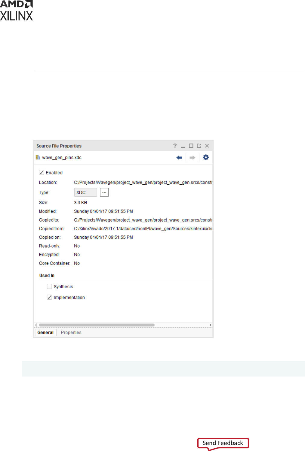
For example, to use a constraint le for implementaon only:
1. Select the constraint le in the Sources window.
2. In the Source File Properes window:
a. Uncheck Synthesis.
b. Check Implementaon.
The equivalent Tcl commands are:
set_property USED_IN_SYNTHESIS false [get_files wave_gen_pins.xdc]
set_property USED_IN_IMPLEMENTATION true [get_files wave_gen_pins.xdc]
When running Vivado in Non-Project Mode, you can read in the constraints directly between any
steps of the ow. The properes USED_IN_SYNTHESIS and USED_IN_IMPLEMENTATION do
not maer in this mode.
Chapter 2: Constraints Methodology
UG903 (v2022.1) June 1, 2022 www.xilinx.com
Using Constraints 11
The following compilaon Tcl script shows how to read two XDC les for dierent steps of the
ow:
read_verilog [glob src/*.v]
read_xdc wave_gen_timing.xdc
synth_design -top wave_gen -part xc7k325tffg900-2
read_xdc wave_gen_pins.xdc
opt_design
place_design
route_design
Table 1: Reading XDC Files Before and After Synthesis
File Name File Placement Used For
wave_gen_timing.xdc Before synthesis
• Synthesis
• Implementation
wave_gen_pins.xdc After synthesis
• Implementation
TIP: The constraints read in aer synthesis are applied in addion to the constraints read in before
synthesis.
Ordering Your Constraints
Because XDC constraints are applied sequenally, and are priorized based on clear precedence
rules, you must review the order of your constraints carefully. For more informaon, see Chapter
7: XDC Precedence.
Note: If mulple physical constraints are conicng, the latest constraint wins. For example, if an I/O port
gets assigned a dierent locaon (LOC) through mulple XDC les, the latest locaon assigned to the port
takes precedence.
The Vivado IDE provides full visibility into your design. To validate your constraints step by step:
1. Run the appropriate report commands.
2. Review the messages in the Tcl Console or the Messages window.
Recommended Constraints Sequence
Whether you use one or several XDC les for your design, organize your constraints in the
following sequence.
## Timing Assertions Section # Primary clocks
# Virtual clocks
# Generated clocks # Clock Groups
# Bus Skew constraints
# Input and output delay constraints
Chapter 2: Constraints Methodology
UG903 (v2022.1) June 1, 2022 www.xilinx.com
Using Constraints 12

## Timing Exceptions Section # False Paths
# Max Delay / Min Delay # Multicycle Paths
# Case Analysis # Disable Timing
## Physical Constraints Section
# located anywhere in the file, preferably before or after the timing
constraints # or stored in a separate constraint file
Note: The case analysis constraints that change the clock relaonships or clock propagaon should be
dened prior to dening the generated clocks. This includes the case analysis dened on clock buers that
result in the output clock of the buer to be impacted by the case analysis.
Start with the clock denions. The clocks must be created before they can be used by any
subsequent constraints. Any reference to a clock before it has been declared results in an error
and the corresponding constraint is ignored. This is true within an individual constraint le, as
well as across all the XDC les (or Tcl scripts) in your design.
The order of the constraint les maers. You must be sure that the constraints in each le do not
rely on the constraints of another le. If this is the case, you must read the le that contains the
constraint dependencies last. If two constraint les have interdependencies, you must either
merge them manually into one le that contains the proper sequence, or divide the les into
several separate les and order them correctly.
Constraints Sequence Editing
The Vivado IDE constraints manager saves any edited constraint back to its original locaon in
the XDC les, but not in Tcl scripts. Any new constraint is saved at the end of the XDC le
marked as target. In many cases, when your constraints set contains several XDC les, the target
constraint le is not the last le in the list, and will not be loaded last when opening or reloading
your design. As a consequence, the constraints sequence saved to constraint source les can be
dierent from the one you had previously in memory.
IMPORTANT!
You must verify that the nal sequence stored in the constraint les sll works as expected.
If you must modify the sequence, you must modify it by directly eding the constraint les. This is
especially important for ming constraints.
Constraint Files Order
In a project ow without any IP, all the constraints are located in a constraints set. By default, the
order of the XDC les (or Tcl scripts) displayed in the Vivado IDE denes the read sequence used
by the tool when loading an elaborated or synthesized design into memory. The le at the top of
the list is read in rst, and the boom one is read in last. You can change the order by simply
selecng the le in the IDE, and moving it to the desired place in the list.
For example, in the following gure, the le wave_gen_pin.xdc was moved to before the le
wave_gen_timing.xdc by using drag and drop.
Chapter 2: Constraints Methodology
UG903 (v2022.1) June 1, 2022 www.xilinx.com
Using Constraints 13
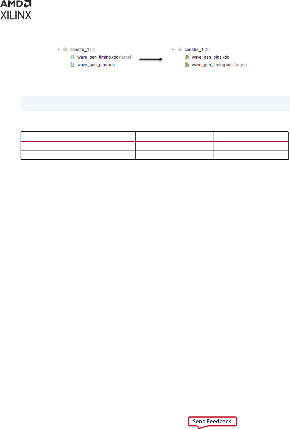
Figure 2: Changing XDC File Order in the Vivado IDE Example
The equivalent Tcl command is:
reorder_files -fileset constrs_1 -before [get_files wave_gen_timing.xdc] \
[get_files wave_gen_pins.xdc]
Table 2: File Order Before and After
File Order (Before) Order (After)
wave_gen_timing.xdc 1 2
wave_gen_pins.xdc 2 1
In Non-Project Mode, the sequence of the read_xdc calls determine the order in which the
constraint les are evaluated.
Constraint Files Order with IP Cores
Many IP cores are delivered with one or more XDC les. When such IP cores are generated
within your RTL project, their XDC les are also used during the various design compilaon
steps.
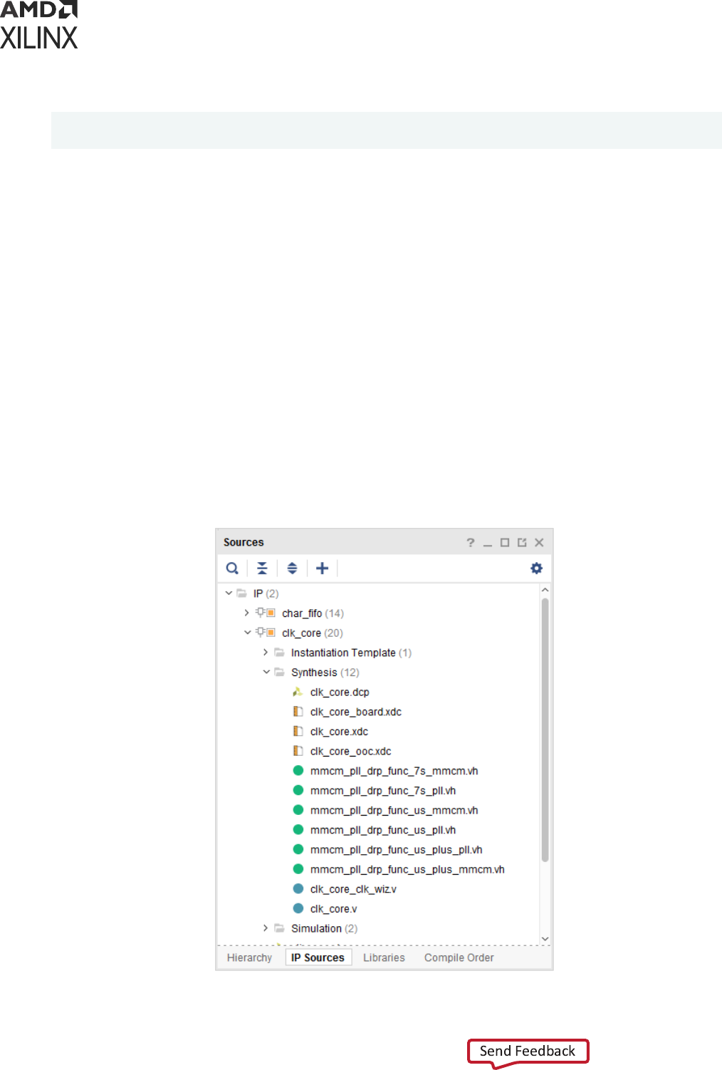
For example, the following gure shows that one of the IP cores in the project comes with an
XDC le.
Chapter 2: Constraints Methodology
UG903 (v2022.1) June 1, 2022 www.xilinx.com
Using Constraints 14
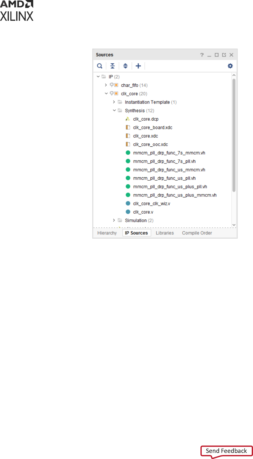
Figure 3: XDC Files in the IP Sources
By default, IP XDC les are read in before the user XDC les. Processing it in this way allows an
IP to create a clock object that can be referenced in the XDC. It also allows you to overwrite
physical constraints set by an IP core because the user constraints are evaluated aer the IP.
There is an excepon to this order for the IP cores that have a dependency on clock objects
being created by the user or by another IP (for example, get_clocks -of_objects
[get_ports clka]). In this case, the IP XDC is read aer the user les.
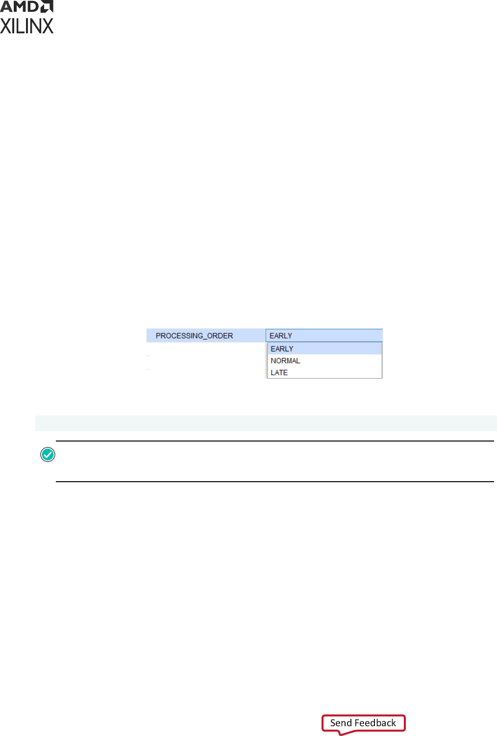
This behavior is controlled by the PROCESSING_ORDER property, set for each XDC le:
• EARLY: Files that must be read rst
• NORMAL: Default
• LATE: Files that must be read last
An IP XDC will have its PROCESSING_ORDER property set to either EARLY or LATE. No IP
delivers XDC les that belong to the NORMAL constraints group. For user XDC (or Tcl) les that
belong to the same PROCESSING_ORDER group, their relave order displayed in the Vivado IDE
determines their read sequence. The order within the group can be modied by moving the les
in the Vivado IDE constraints set, or by using the reorder_files command.
Chapter 2: Constraints Methodology
UG903 (v2022.1) June 1, 2022 www.xilinx.com
Using Constraints 15
For IP XDC les that belong to the same PROCESSING_ORDER group, the order is determined
by import or creaon sequence of the IP cores. This order cannot be changed aer the project
has been created.
Finally, the relave order between user groups and IP XDC PROCESSING_ORDER groups are as
follows:
1. User Constraints marked as EARLY
2. IP Constraints marked as EARLY (default)
3. User Constraints marked as NORMAL
4. IP Constraints marked as LATE (contain clock dependencies)
5. User Constraints marked as LATE
Note: IP XDC les that have their PROCESSING_ORDER set to LATE (in order to be processed aer the
user constraints) are named <IP_NAME>_clocks.xdc.
The following gure shows an example of how to set the PROCESSING_ORDER property:
Figure 4: Setting the XDC File PROCESSING_ORDER Example
The equivalent Tcl command is:
set_property PROCESSING_ORDER EARLY [get_files wave_gen_pins.xdc]
RECOMMENDED:
Use the
report_compile_order -constraints
command in the Tcl Console
to report the XDC les read sequence determined by the tool based the properes menoned above,
including IS_ENABLED, USED_IN_SYNTHESIS, and USED_IN_IMPLEMENTATION.
Note: When an IP is synthesized Out of Context, the IP provides, when needed, an _ooc.xdc le which
contains the default clock denion. The _ooc.xdc has the USED_IN property set to "synthesis
out_of_context implementaon" (order does not maer). During the Out Of Context synthesis, the _ooc
le is always processed before all other constraints.
Changing Read Order
To change the read order of an XDC le or unmanaged Tcl script in a constraints set:
1. In the Sources window, select the XDC le or Tcl script you want to move.
2. Drag and drop the le to the desired posion in the constraints set.
Chapter 2: Constraints Methodology
UG903 (v2022.1) June 1, 2022 www.xilinx.com
Using Constraints 16
For the example shown in Figure 2, the equivalent Tcl command is:
reorder_files -fileset constrs_1 -before [get_files wave_gen_timing.xdc] \
[get_files wave_gen_pins.xdc]
In Non-Project Mode, the sequence of the read_xdc or source commands determines the order
the constraint les are read.
If you use an IP core that comes with constraints, two groups of constraints are handled
automacally as follows:
• Constraints that do not depend on clocks are grouped in an XDC le with
PROCESSING_ORDER set to EARLY,
• Constraints that depend on clocks are grouped in an XDC le with PROCESSING_ORDER set
to LATE.
By default, user XDC les belong to the PROCESSING_ORDER NORMAL group. They are loaded
aer EARLY XDC les and before LATE XDC les. For each PROCESSING_ORDER group, IP
XDC les are loaded in the same sequence as how the IP cores are listed in the IP Sources
window. For example, the following gure shows one of the project IP cores that comes with an
XDC le.
Figure 5: XDC Files in the IP Sources
Chapter 2: Constraints Methodology
UG903 (v2022.1) June 1, 2022 www.xilinx.com
Using Constraints 17

When you open your design, the log le shows that the IP XDC le was loaded last:
Parsing XDC File [C:/project_wave_gen_hdl.srcs/sources_1/ip/clk_core/
clk_core.xdc] for cell 'clk_gen_i0/clk_core_i0/inst'
Finished Parsing XDC File [C:/project_wave_gen_hdl.srcs/sources_1/ip/
clk_core/clk_core.xdc] for cell 'clk_gen_i0/clk_core_i0/inst'
Parsing XDC File [C:/project_wave_gen_hdl.srcs/sources_1/ip/char_fifo/
char_fifo/char_fifo.xdc] for cell 'char_fifo_i0/U0'
Finished Parsing XDC File [C:/project_wave_gen_hdl.srcs/sources_1/ip/
char_fifo/char_fifo/char_fifo.xdc] for cell 'char_fifo_i0/U0'
Parsing XDC File [C:/project_wave_gen_hdl.srcs/constrs_1/imports/verilog/
wave_gen_timing.xdc] Finished Parsing XDC File [C:/
project_wave_gen_hdl.srcs/constrs_1/imports/verilog/wave_gen_timing.xdc]
Parsing XDC File [C:/project_wave_gen_hdl.srcs/sources_1/ip/char_fifo/
char_fifo/char_fifo_clocks.xdc
] for cell 'char_fifo_i0/U0'
Finished Parsing XDC File [C:/project_wave_gen_hdl.srcs/sources_1/ip/
char_fifo/char_fifo/char_fifo_clocks.xdc
] for cell 'char_fifo_i0/U0' Completed Processing XDC Constraints
Unlike with the User XDC les, you cannot directly change the read order of the IP XDC les that
belong to the same PROCESSING_ORDER group. If you must modify the order, do the following:
1. Disable the corresponding IP XDC les (IS_ENABLED set to false).
2. Copy their content.
3. Paste the content into one of the XDC les included in your constraints set.
4. Update the copied IP XDC commands with the full hierarchical netlist object path names
wherever needed. Doing so is required because the IP XDC constraints are wrien in such a
manner that they can be scoped to the IP instance.
5. Review the get_ports queries that are processed in a special way for scoped constraints. For
more informaon on XDC scoping, see Constraints Scoping.
Entering Constraints
The Vivado IDE provides several ways to enter constraints. Unless you directly edit the XDC le
in a text editor, you must open a design database (elaborated, synthesized or implemented) in
order to access the constraints windows in the Vivado IDE.
Saving Constraints in Memory
You must have a design in memory to validate your constraints during eding. When you edit a
constraint using the Vivado IDE user interface, the equivalent XDC command is issued in the Tcl
Console in order to apply it in memory. An edited ming constraint must be applied in memory
before it can be saved to the XDC le.
Chapter 2: Constraints Methodology
UG903 (v2022.1) June 1, 2022 www.xilinx.com
Using Constraints 18

Before you can run synthesis or implementaon, you must save the constraints in memory back
to an XDC le that belongs to the project. The Vivado IDE prompts you to save your constraints
whenever necessary.
Do one of the following to save your constraints manually:
• Click Save Constraints.
• Select File → Constraints → Save.
Note: When you save the in-memory constraints, a dialog box opens to remind you that this could cause
the synthesis and implementaon to go out of date. Select the Remember Preference check box on this
dialog box to disable future instances of this warning.
When you run these commands, Vivado does the following:
• Saves all new constraints to the XDC le marked target in the constraints set associated with
your design.
• Saves all edited constraints back to the XDC le from which they originated.
Note: The constraints management system preserves the original XDC les format as much as possible.
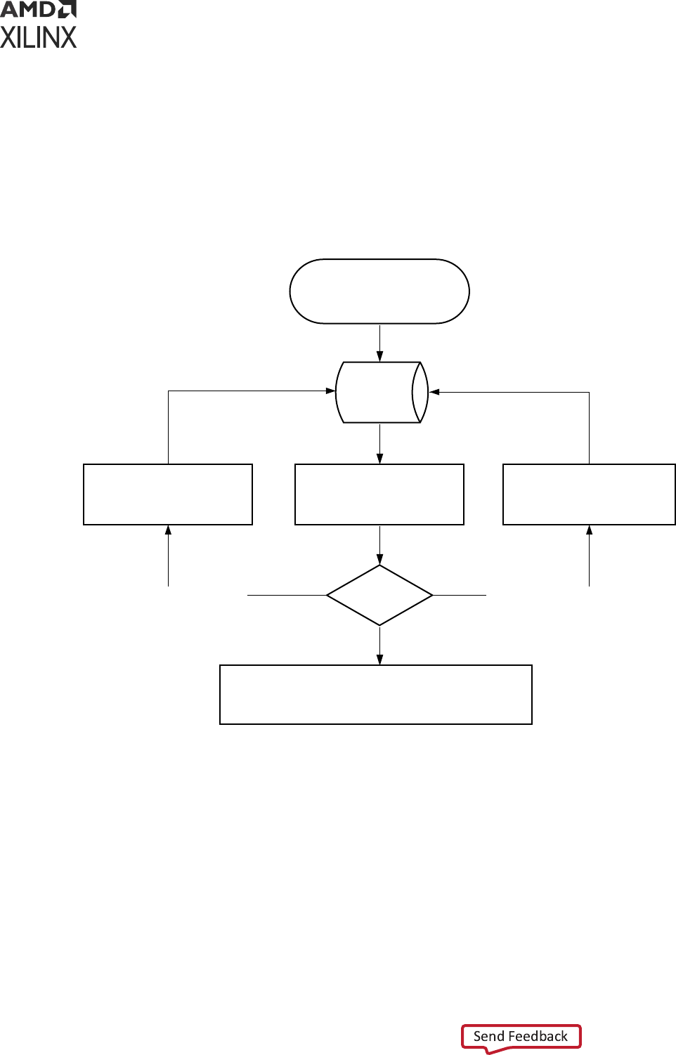
Constraints Editing Flow Options
Figure 6 shows the recommended ow opons. Do not use both opons at the same me.
Mixing these opons might cause you to lose constraints. The recommended ow opons are:
• User Interface Opon
• Hand Edit Opon
User Interface Option
Because the Vivado IDE manages your constraints, you must not edit your XDC les at the same
me. When the Vivado IDE saves the memory content, the following occurs:
• The modied constraints replace the original constraints in their original le.
• The new constraints are appended to the le marked as target.
• All manual edits in the XDC les are overwrien.
Hand Edit Option
When you use the Hand Edit opon, you are in charge of eding and maintaining the XDC les.
While you will probably use the Tcl Console to verify the syntax of some constraints, you must
discard the changes made in memory when closing or reloading your design.
In case of a conict when saving the constraints, you are prompted to choose one of the
following:
Chapter 2: Constraints Methodology
UG903 (v2022.1) June 1, 2022 www.xilinx.com
Using Constraints 19
• Discarding the changes made in memory
• Saving the changes in a new le
• Overwring the XDC les
Constraints creaon is iterave. You can use IDE editors in some cases, and hand edit the
constraint les in others.
Figure 6: Constraints Editing Flow
Load your design in memory
Vivado
Database
Analyze your design
schematics/Device/
Reports)
Need more
constraints
?
Use Vivado IDE editors
(Device/Physical/Timing/
Others...) or Tcl Console
1. Edit XDC files in Text Editor
2. Save your XDC files
3. Reload your design
Close your design / Run compilation:
GUI Option: save changes to XDC file(s) (new or existing)
Hand Edit Option: do nothing (or discard any changes)
NO
YES (GUI Option) YES (Hand Edit Option)
X12983
Within each iteraon described in the previous gure, do not use both opons at the same me.
If you switch between the two opons, you must rst save your constraints or reload your
design, to ensure that the constraints in memory are properly synchronized with the XDC les.
Pin Assignment
To create and edit exisng top-level ports placement when using the RTL Analysis, Synthesis, or
Implementaon views:
1. Select the I/O Planning pre-congured layout.
Chapter 2: Constraints Methodology
UG903 (v2022.1) June 1, 2022 www.xilinx.com
Using Constraints 20
2. Open the windows shown in the following table:
Table 3: Creating and Editing Existing Top-Level Ports Placement
Window Function
Device View and edit the location of the ports on the device floorplan.
Package View and edit the location of the ports on the device package.
I/O Ports Select a port, drag and drop it to a location on the Device or Package
view, as well as review current assignment and properties of each port.
Package Pins View the resource utilization in each I/O bank.
For more informaon on Pin Assignment, see this link in the Vivado Design Suite User Guide: I/O
and Clock Planning (UG899).
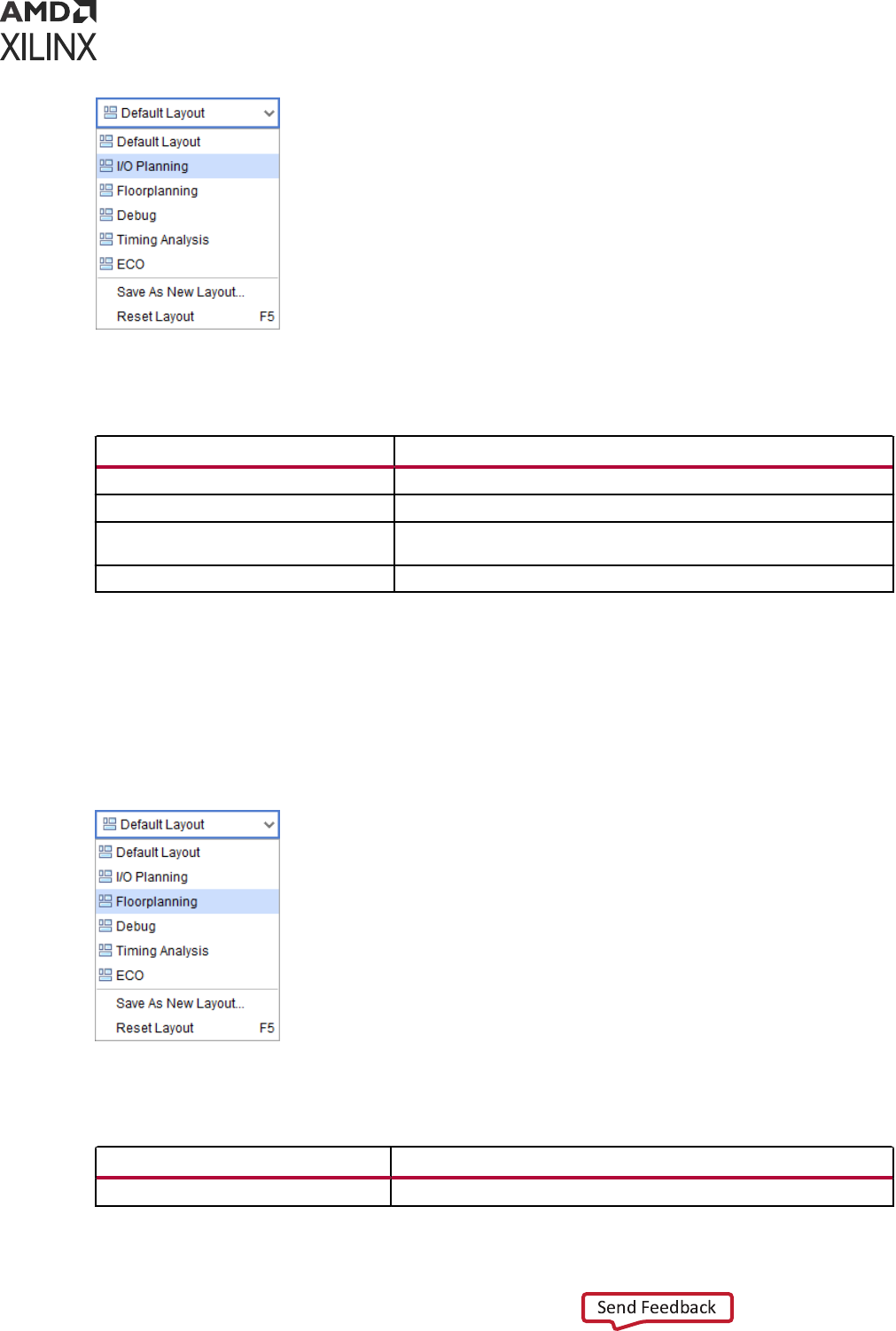
Floorplanning
To create and edit Pblocks when using the RTL Analysis, Synthesis, or Implementaon views:
1. Select the Floorplanning pre-congured layout.
2. Open the windows shown in the following table.
Table 4:
Creating and Editing Pblocks
Window Function
Netlist Select the cells to be assigned to a Pblock.
Chapter 2: Constraints Methodology
UG903 (v2022.1) June 1, 2022 www.xilinx.com
Using Constraints 21
Table 4: Creating and Editing Pblocks (cont'd)
Window Function
Physical Constraints Review the existing Pblocks and their properties.
Device Create or edit the shape and location of your Pblocks in the device.
To create cell placement constraints on a parcular BEL or SITE:
1. Select the cell in the Netlist view.
2. Drag and drop the cell to the target locaon in the Device view.
For more informaon on Floorplanning, see this link in the Vivado Design Suite User Guide: Design
Analysis and Closure Techniques (UG906).
Timing Constraints Wizard
The Timing Constraints Wizard idenes missing ming constraints on a synthesized or
implemented design. It analyzes the netlist, the clock nets connecvity, and the exisng ming
constraints in order to provide recommendaons as per the UltraFast Design Methodology Guide
for Xilinx FPGAs and SoCs (UG949). Three categories of constraints are covered by the following
11 pages of the wizard, followed by a summary. The following steps are included:
• Clocks
○ Primary clocks
○ Generated clocks
○ Forwarded clocks
○ External feedback delays
• Input and output ports
○ Input delays
○ Output delays
○ Combinatorial delays
• Clock domain crossing
○ Physically exclusive clock groups
○ Logically exclusive clock groups with no interacon
○ Logically exclusive clock groups with interacon
○ Asynchronous clock domain crossings
• Constraints summary
Chapter 2: Constraints Methodology
UG903 (v2022.1) June 1, 2022 www.xilinx.com
Using Constraints 22
During each step, you can accept the recommended constraints or modify the list by checking or
unchecking each of the proposed constraints. However, unchecking recommended constraints
early in the wizard can prevent the idencaon of other missing constraints in subsequent
steps. For example, if you decide to skip the creaon of a clock, the wizard will not idenfy and
recommend any constraints that refer to this clock or its auto-derived clocks.
The nal page of the wizard provides a summary of the constraints that will be created. You can
click on each individual hyperlink to see the constraints details, or visualize the new constraints in
the Timing Constraints window aer exing the wizard.
You can also choose to generate the following recommended reports upon clicking Finish to
verify that the design is completely and properly constrained:
• Create Timing Summary report: Timing slack is reported with the new constraints, in addion
to a check_ming report. Timing violaons will likely display if the period or I/O delay
constraints that you entered are too dicult.
• Create Check Timing report: This report idenes missing or inappropriate constraints by
running the check_timing command.
• Create DRC Report using only Timing Checks: This report runs the Timing DRCs.
IMPORTANT!
The newly added constraints are automacally saved to the Target XDC le unless you click
Cancel. You can edit or delete the new constraints in the Timing Constraints window aer exing the
wizard.
The Timing Constraint Wizard does not recommend a constraint if it introduces unsafe ming
analysis. Also, the wizard does not x inappropriate constraints that already existed when loading
the design in memory. Nevertheless, some invalid constraints might become valid aer creang
all the missing clocks when using Vivado Design Suite in project mode; for more details, see
Constraints Processing Order and Invalid Constraints, below. Also, aer using the wizard, if
check_timing or report_drc sll ag some constraints issues, it is usually due to a
constraint problem that already existed in the source XDC les. You must address these problems
directly instead of using the wizard to resolve them.
VIDEO:
For more informaon on the Vivado Timing Constraints Wizard, see Vivado Design Suite
QuickTake Video: Using the Vivado Timing Constraint Wizard.
Constraints Processing Order and Invalid Constraints
The Timing Constraints Wizard recommends missing constraints that dene clocks or refer to
clocks, which will be saved either at the end of the target XDC le in project mode, or at the end
of all constraints in other modes. For this reason, you must understand the following rules:
Chapter 2: Constraints Methodology
UG903 (v2022.1) June 1, 2022 www.xilinx.com
Using Constraints 23

• Project mode: You must specify a target XDC le with its processing order set to NORMAL
before launching the Timing Constraints wizard. The target XDC le must belong to the
Constraints Set of the design open in memory and currently selected. The posion of the
target XDC le among the other XDC les maers because it species where the
recommended constraints will be applied and saved later. Also, the wizard tries to re-apply any
invalid constraint that belongs to XDC les parsed aer the target XDC le in order to provide
the most complete and accurate recommendaons.
For example, consider the netlist from synth_1 run open in memory with the Constraints Set
constr_1. This Constraints Set contains three XDC les in the sequence a.xdc, b.xdc, and
c.xdc. If you choose b.xdc as the target XDC le and each le contains an invalid
constraint, the Timing Constraints wizard applies the recommended clocks, then re-applies the
invalid constraints from c.xdc before proceeding to the next step and discovering other
missing constraints.
• Non-project or Design Check Point (DCP) modes: You cannot specify a target XDC le in
these modes, so the Timing Constraints wizard recommends and applies new constraints at
the last posion of the constraints sequence. This is equivalent to entering new constraints in
the Tcl Console or via the Timing Constraints window. In these modes, the wizard does not
aempt to re-apply invalid constraints. If the new constraints need to be applied earlier in the
overall constraints sequence in order to resolve constraints dependencies or precedence
issues, you must edit the constraints sequence manually.
Here is an example of how to manually edit constraints.
1. Create new constraints using the Vivado Design Suite.
2. Run one of the following commands:
write_xdc -exclude_physical timing_constraints.xdc write_xdc -type
timing timing_constraints.xdc
3. Edit timing_constraints.xdc to move the new constraints higher in the XDC le.
4. Save the le.
5. Run the following command:
reset_timing
6. Read the edited ming constraints le by typing:
read_xdc timing_constraints.xdc
You can review the updated ming constraints sequence using the Timing Constraints window.
Aer reviewing the new constraints, you can save the sequence into the DCP.
Chapter 2: Constraints Methodology
UG903 (v2022.1) June 1, 2022 www.xilinx.com
Using Constraints 24
Reporting Features Available When the Wizard is Open
When the Timing Constraints wizard is open, it prevents most acons in the Vivado IDE,
including using the Tcl Console or running ming analysis, in order to avoid database
discrepancies. The wizard window is always in front of the other Vivado IDE windows. If you
need to access the Vivado IDE menus or windows, you must move the wizard window to the
side.
Only the following features are available while the Timing Constraints wizard is open:
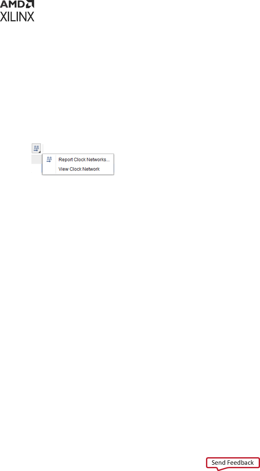
• Reporng and visualizing the clock networks: Most pages of the wizard have buons to
generate and access the clock network report to visualize the clock topologies, their source
point, and the shared segments for some of the clocks.
Refer to the Vivado Design Suite User Guide: Design Analysis and Closure Techniques (UG906) for
more details about the clock network report.
• Searching a name in source les or an object in the design in memory: The Find and Find In
Files dialog boxes are available from the Edit menu. You can use these dialog boxes to retrieve
some informaon about the design while entering the constraints in the wizard.
• Creang and Viewing schemacs: You can select design objects in the main Vivado IDE
window and visualize them in schemacs. All schemacs features are available. Only the last
step of the Timing Constraints wizard, Asynchronous Clock Domain Crossings, supports
convenient schemacs cross-probing when selecng one or several entries in the Timing
Paths tab.
Refer to the Vivado Design Suite User Guide: Using the Vivado IDE (UG893) for more info on
using schemacs.
• Visualizing constraints in memory with the Timing Constraints window: Each page of the
wizard includes a tab that shows the exisng constraints of the same type as recommended
by the step. This is convenient for quickly reviewing the details of constraints already created
in the XDC les. For a complete view of all ming constraints in memory, the Timing
Constraints window shows the full sequence of constraints, organized by XDC le, including
scoping informaon. It also displays the invalid constraints.
Constraints Editing within the Wizard
Each step of the wizard can recommend several constraints. Depending on the constraint, you
must take one of the following acons:
• Uncheck the constraints you do not want to create, using one of the following methods:
○ Remove each constraint from the list, one at a me, by unchecking each line.
Chapter 2: Constraints Methodology
UG903 (v2022.1) June 1, 2022 www.xilinx.com
Using Constraints 25
○ Remove all constraints by unchecking the upper le check box of the table.
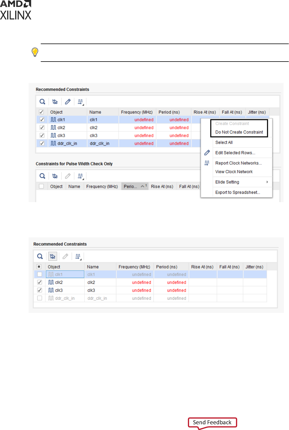
TIP: Alternavely, you can right-click the constraint, and select Do Not Create Constraint, as shown in
the following gure.
Figure 7: Skipping Recommended Constraints Using the Context Menu
In the following gure, clk1 and ddr_clk_in are unchecked and will be skipped.
Figure 8: Creating and Skipping Recommended Constraints
• Enter the missing values by clicking on the cells that show undened (for example, the
Frequency or Period value for clk2 and clk3 in the previous gure).
You can edit several constraints at the same me by selecng the corresponding rows and
clicking the Edit Selected Rows buon, as shown in the following gure.
Chapter 2: Constraints Methodology
UG903 (v2022.1) June 1, 2022 www.xilinx.com
Using Constraints 26
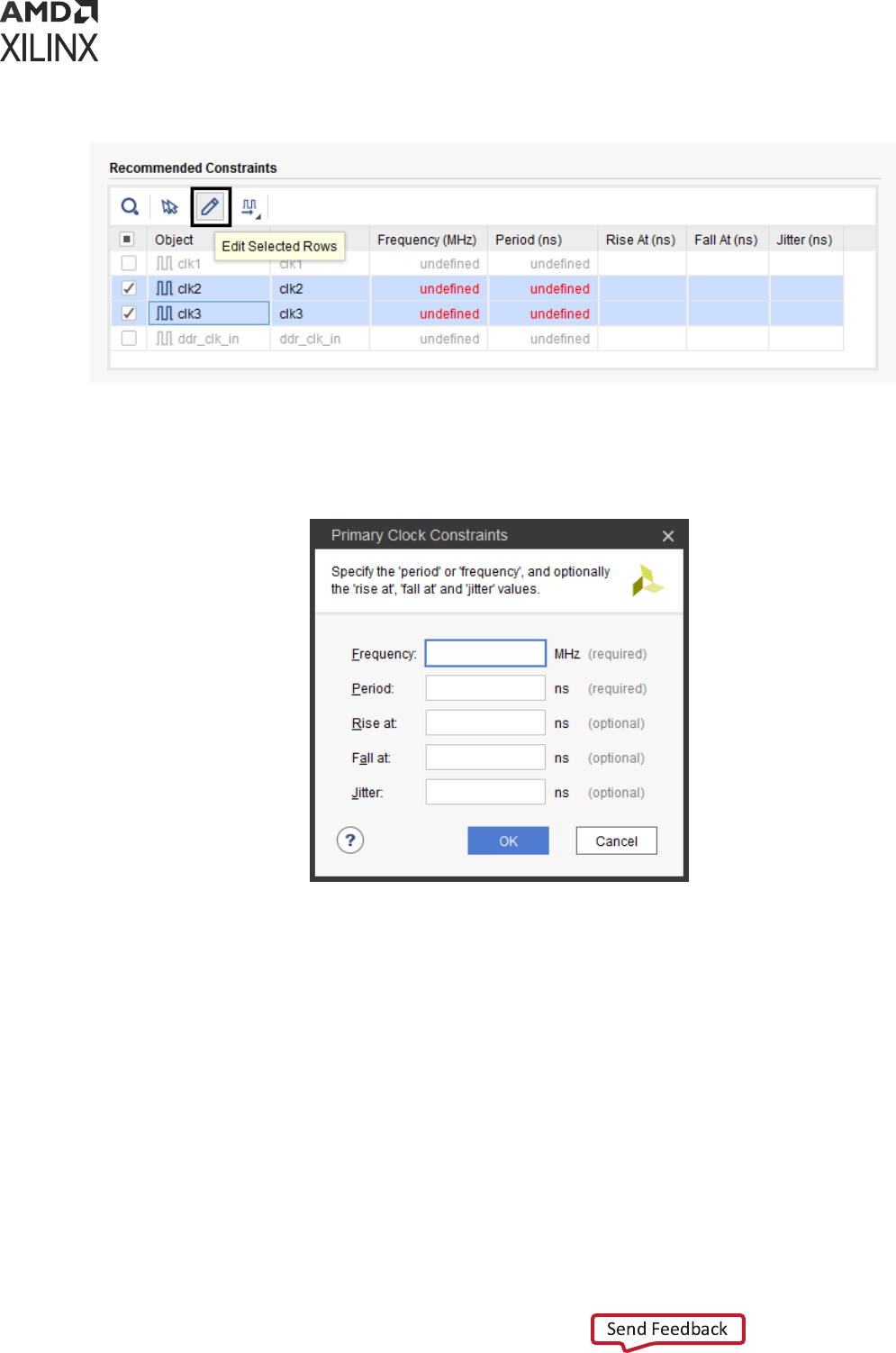
Figure 9: Editing Several Recommended Constraints
Next, ll out any required elds, such as Frequency and Period as shown in the following
gure:
Figure 10: Entering Parameters for Several Recommended Constraints
Eding mulple constraints at a me is parcularly helpful for input and output delay
constraints.
• Simply review the constraints if no acon is required.
When all the checked recommended constraints have been reviewed and completed, click Next
to proceed to the next page. Any entries that you missed prevent the wizard from moving to the
next step.
You can use the Back buon to revisit a page. If you edit any constraint on a previous page and
click Next, the wizard re-analyzes the design and recommends new constraints accordingly. In
most cases, the previously recommended constraints not aected by the change are reinstated. If
you only view a previous page without modifying any of its recommended constraints, the wizard
does not re-run any analysis, which usually saves runme.
Chapter 2: Constraints Methodology
UG903 (v2022.1) June 1, 2022 www.xilinx.com
Using Constraints 27
IMPORTANT! You cannot use the Timing Constraints wizard to edit exisng ming constraints. Instead,
you must use the Timing Constraints window.
Constraints Recommended by the Wizard
Primary Clocks
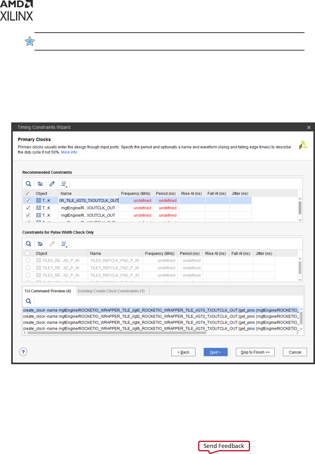
Two categories of clocks are idened by the wizard, as shown in the following gure:
Figure 11: Recommended Primary Clocks
• The primary clocks needed for compung the ming slack for setup, hold, recovery, and
removal checks appear in the Recommended Constraints table.
Chapter 2: Constraints Methodology
UG903 (v2022.1) June 1, 2022 www.xilinx.com
Using Constraints 28

• The clocks only needed for performing pulse width checks (min_period, max_period,
max_skew, min_low_pulse_width, and min_high_pulse_width) appear in the Constraints For
Pulse Width Check Only table. By default, these clocks are unchecked because they are only
used for reporng purposes and do not inuence the implementaon tools quality of result.
The wizard automacally idenes the proper clock source point for the constraint. In most
cases, the clock source point is an input clock port, and in some special cases it is the output of a
primive that does not have a ming arc. For example, in 7 series devices, the wizard idenes
missing primary clocks on the output of GT_CHANNEL primives. For UltraScale™ devices, the
Vivado Design Suite is able to auto-derive the GT_CHANNEL output clocks based on the
incoming clock characteriscs and the GT_CHANNEL conguraon and connecvity.
Consequently, the wizard recommends primary clocks located upstream from the GT_CHANNEL
cells on the design boundary.
Generated Clocks
The Timing Constraints wizard recommends the creaon of a generated clock on the output of a
sequenal cell when it drives the clock pins of other sequenal cells either directly or through
some interconnect logic. Unlike PLL or MMCM, user logic cannot mulply the frequency of the
master clock, so the wizard only oers the opon to specify a division coecient, as shown in
the following gure:
Chapter 2: Constraints Methodology
UG903 (v2022.1) June 1, 2022 www.xilinx.com
Using Constraints 29
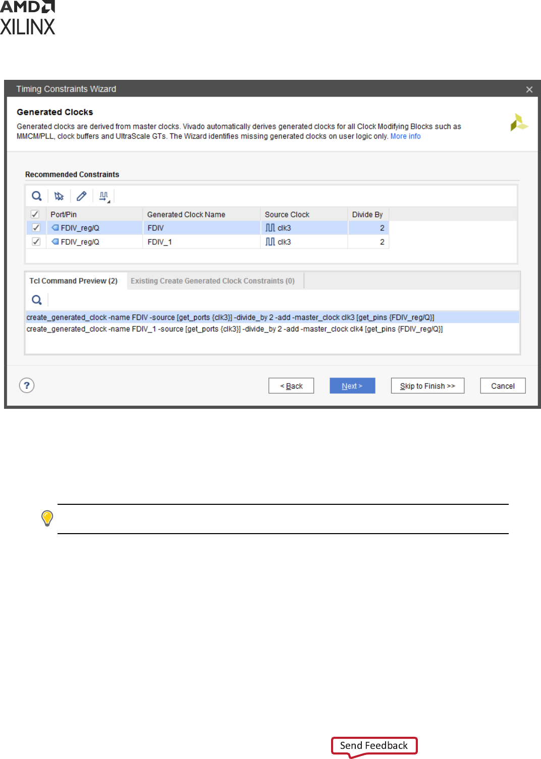
Figure 12: Generated Clocks Page of the Timing Constraints Wizard
When several master clocks reach the generated clock source point, the wizard creates all the
corresponding generated clocks, using unique names and clear reference to individual master
clocks. The previous gure illustrates the scenario where two clocks (clk3 and clk4) reach the
sequenal cell FDIV_reg. Consequently, two generated clock constraints (FDIV and FDIV_1) are
recommended.
TIP:
Some clocking topologies, such as cascaded registers on the clock path, might require that you run the
Timing Constraints wizard mulple mes to discover all the missing generated clocks.
Forwarded Clocks
The Timing Constraints wizard recommends generated clock constraints on output ports that are
driven by double data-rate registers with constant inputs. Based on the input constant
connecvity, the generated clock phase is adjusted to either posive (0 degree phase shi) or
inverted (180 degree phase shi). The master clock used in the constraint is the clock that
reaches the clock pin of the double data-rate register. See the Source Clock column of the
Recommended Constraints table in the following gure:
Chapter 2: Constraints Methodology
UG903 (v2022.1) June 1, 2022 www.xilinx.com
Using Constraints 30
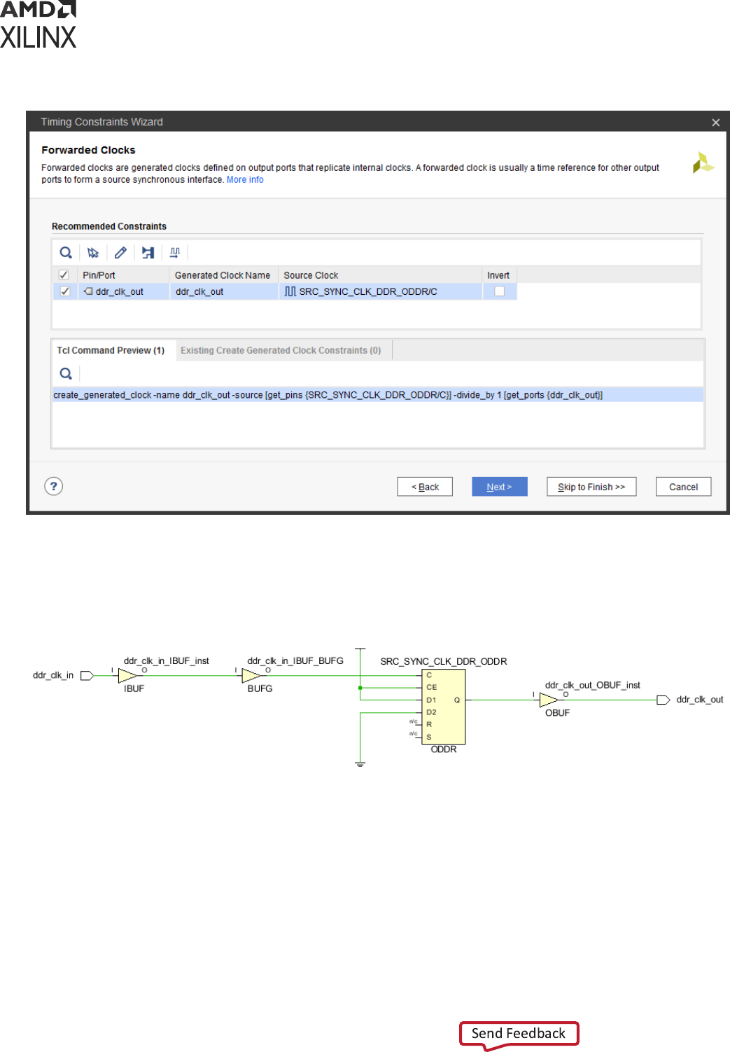
Figure 13: Recommended Forwarded Clocks
For the 7 series device family, the topology recognized by the wizard is shown in the following
gure. There is no restricon on the nature of the master clock or the output buer.
Figure 14: 7 Series Forwarded Clock Typical Circuitry
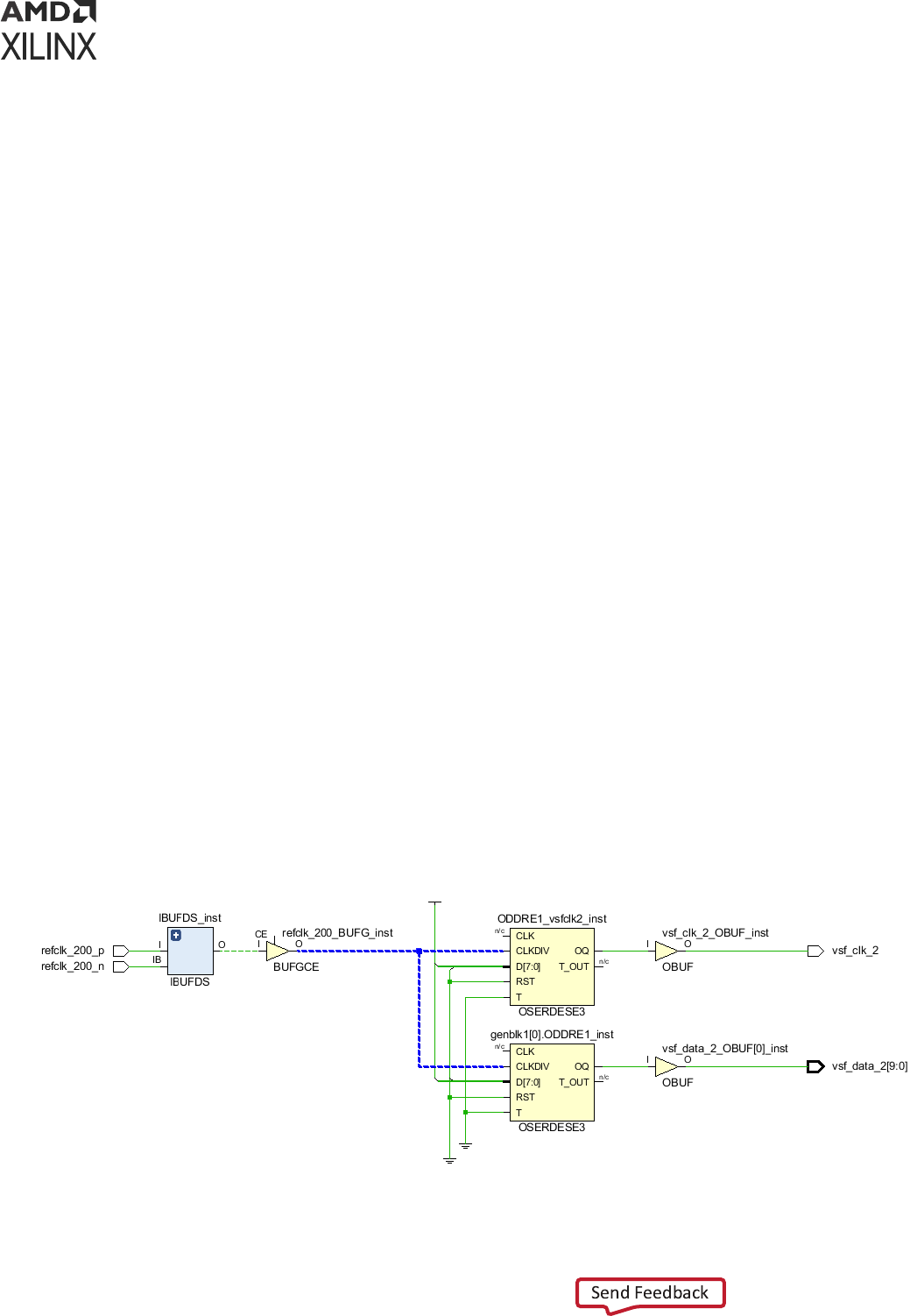
For the UltraScale device family, the ODDR and ODDRE1 primives are automacally retargeted
to OSERDESE3 with the property ODDR_MODE=TRUE. The wizard recognizes the topology
shown in the following gure, where OSERDESE3/D[0] is connected to 1 and OSERDESE3/D[4]
is connected to 0 (no phase-shi).
Chapter 2: Constraints Methodology
UG903 (v2022.1) June 1, 2022 www.xilinx.com
Using Constraints 31

Figure 15: UltraScale Forwarded Clock Typical Circuitry
External Feedback Delays
The Timing Constraints wizard analyzes the feedback loop connecvity of the MMCM and PLL
cells present in the design. External delay constraints (min and max) are recommended when the
CLKFBIN and CLKFBOUT pins are connected to the design ports through IO buers and the
MMCM or PLL property COMPENSATION=EXTERNAL. The following gure illustrates the
recommended External Delay constraints.
Figure 16: Recommended External Delay Constraints
The following gure illustrates a typical MMCM with external feedback path circuit.
Chapter 2: Constraints Methodology
UG903 (v2022.1) June 1, 2022 www.xilinx.com
Using Constraints 32
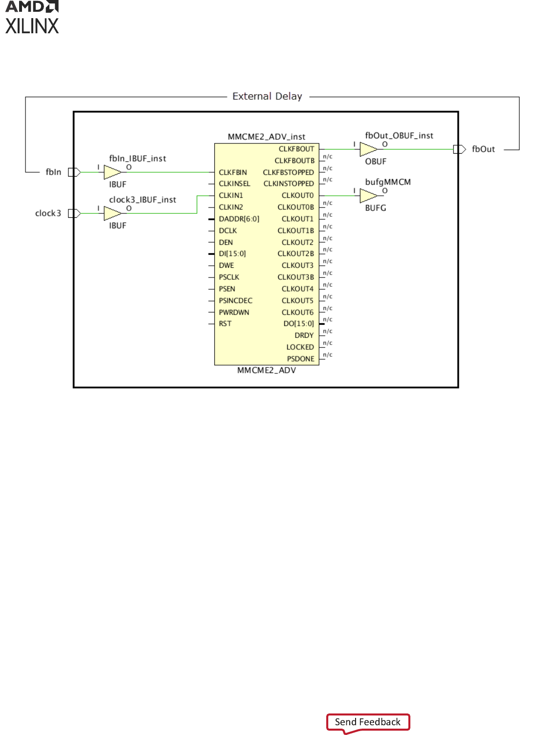
Figure 17: Typical MMCM External Feedback Path Circuit
In the current Vivado Design Suite release, the Timing Constraints wizard cannot recommend
external delay constraints when there is a sequenal cell in the feedback path, such as ODDR,
which is used for generang a forwarded clock. In this case, you must create the external delay
constraints manually or using the Timing Constraints window aer exing the wizard.
Input Delays
The Timing Constraints wizard analyzes all paths from input ports to idenfy their desnaon
clock inside the design and their acve edges. Based on this informaon, the wizard recommends
basic system synchronous input delay constraints that are based on the XDC templates available
in the Vivado IDE (see XDC Templates for templates). The waveform associated with the selected
template is displayed at the boom of the window in the Waveform tab when you select a
constraint entry in the Recommended Constraints table.
The following gure shows an example of several input constraints proposed by the wizard and
parally edited by the user.
Chapter 2: Constraints Methodology
UG903 (v2022.1) June 1, 2022 www.xilinx.com
Using Constraints 33
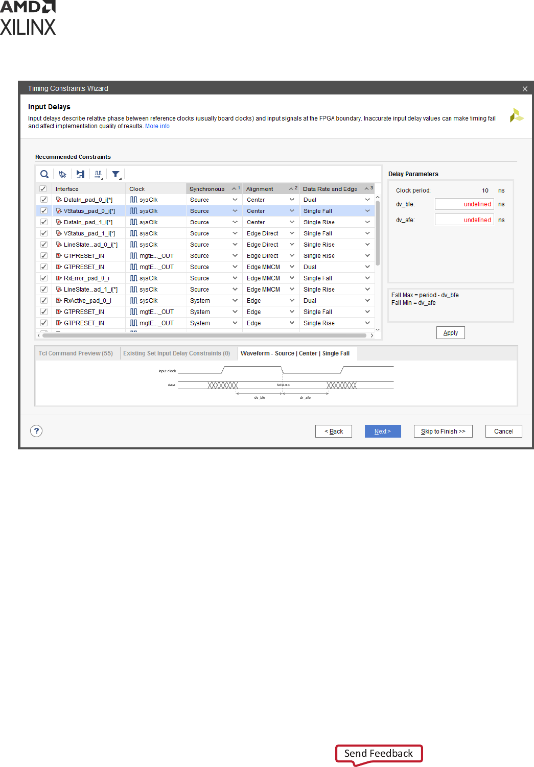
Figure 18: Recommended Input Delay Constraint Templates
For each constraint, you can edit three characteriscs in order to specify the appropriate
waveform that corresponds to the actual interface ming on the board:
• Synchronous: Describes the nature of the clock-data relaonship.
• System (for System Synchronous interface): Use this seng when the data is launched and
captured by dierent clock edges that are 1 period or ½ period apart.
• Source (for Source Synchronous interface): Use this seng when the data is launched and
captured by the same clock edge.
• Alignment: Describes the data transion alignment with respect to the acve clock edge.
• For System Synchronous interfaces only:
• Edge: Use this seng when the clock and data transion at the same me.
Chapter 2: Constraints Methodology
UG903 (v2022.1) June 1, 2022 www.xilinx.com
Using Constraints 34

• For Source Synchronous interfaces only:
• Center: Use this seng when the clock transions in the middle of the data valid
window.
• Edge Direct: Use this seng when the clock transions at the beginning of the data
valid window.
• Edge MMCM: Use this seng when the clock transions at the end of the data valid
window.
• Data Rate and Edge : Describes the acve clock edges constrained by the template. The
default value recommended by the wizard is based on the acve clock edges of the capturing
sequenal cell.
• Single Rise: Use this seng for cases where only the rising clock edges launch the data
outside the FPGA.
• Single Fall: Use this seng for cases where only the falling clock edges launch the data
outside the FPGA.
• Dual: Use this seng for cases where both rising and falling clock edges launch the data
outside the FPGA.
The recommended clock is usually the board clock related to the input path sequenal cell.
When the input path internal clock is an MMCM or PLL generated clock, the board clock that
drives the MMCM or PLL is used as the input constraint reference clock. The only excepons
exist when the internal clock waveform and the board clock waveform are not idencal, such as
the following scenarios:
• Dierent period scenario: The input constraint references a virtual clock that has the same
waveform as the internal clock so that the setup analysis is performed with a 1 cycle path
requirement. The virtual clock is automacally created.
• Posive phase-shi clock scenario: The wizard uses a virtual clock as the reference clock. The
virtual clock is automacally created with the same waveform as the board clock. In addion,
the wizard also species a mulcycle path constraint between the virtual clock and the
internal clock to adjust the default analysis to 1 period + the amount of phase-shi for setup.
The combinaon of the virtual clock and the mulcycle path constraint provides simpler
constraints for the Vivado Design Suite mer to handle and can only aect input ports that
reference to the virtual clock.
Note that for a negave phase-shi, the virtual clock and the mulcycle path constraint are
not needed because the default setup path requirement is 1-cycle minus the amount of
phase-shi.
The wizard does not allow you to change the reference clock selected for the constraint. To do
so, you must manually edit the XDC les or use the Timing Constraints window aer exing the
wizard.
Chapter 2: Constraints Methodology
UG903 (v2022.1) June 1, 2022 www.xilinx.com
Using Constraints 35
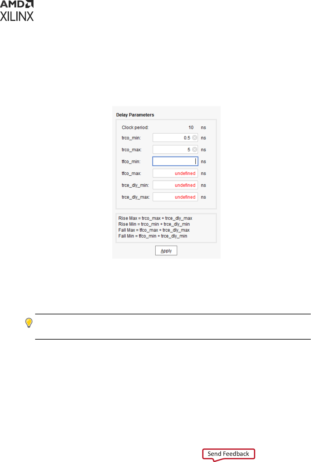
Aer you select the proper template, enter the delay parameter values in the Delay Parameters
panel located on the right hand side of the wizard and then click Apply to validate the entries.
The input delay equaons are displayed below the delay parameter elds and on some of the
template waveforms. The following gure shows the Delay Parameters panel for the DDR
System Synchronous interface template.
Figure 19: Input Delay Parameters Panel
To accelerate the delay parameter entry task, you can select and edit several constraints with
same clock and same template at once.
Aer the constraints have been completed and applied, you can review their corresponding Tcl
syntax in the Tcl Command Preview tab or you can click Next to proceed to the next step.
TIP:
The Timing Constraints wizard skips input ports with a false path constraint. This is parcularly useful
for skipping asynchronous resets that usually do not have a known phase relaonship with any clock of the
design. The false path constraint can only be created outside the wizard.
Output Delays
Similar to the Input delays step, the Timing Constraints wizard analyzes the paths to all output
ports to idenfy their source clocks inside the design and their acve edges. The template
selecon rules are the same as described in Input Delays. The following gure shows several
output constraints proposed by the wizard and parally edited by the user.
Chapter 2: Constraints Methodology
UG903 (v2022.1) June 1, 2022 www.xilinx.com
Using Constraints 36
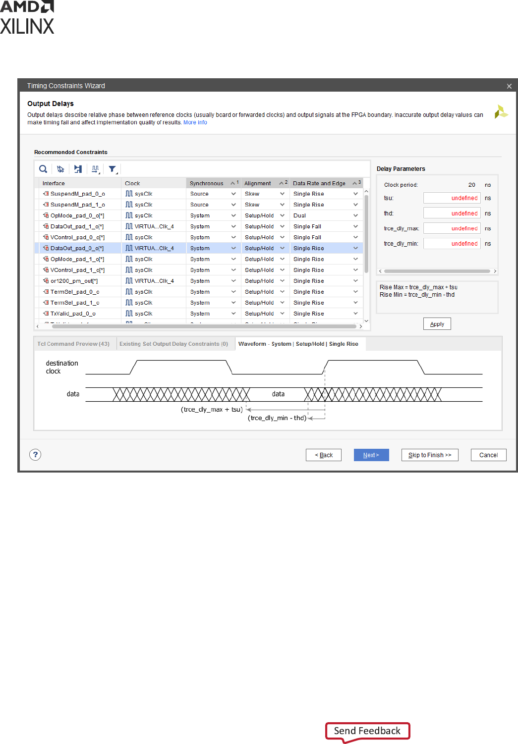
Figure 20: Recommended Output Delay Constraint Templates
For each constraint, three characteriscs can be edited in order specify the appropriate
waveform that corresponds to the actual interface ming on the board:
• Synchronous: Describes the nature of the clock-data relaonship (see Input Delays for more
details).
• Alignment: Describes the data transion alignment with respect to the acve clock edge.
• Setup/Hold: Use this seng when the template delay parameters are specied based on
the data valid window ming characteriscs outside the FPGA.
• Skew (Source Synchronous only): Use this seng when the template delay parameters are
specied based on the skew requirements on the output pin of the FPGA.
• Data Rate and Edge: Describes the acve clock edges constrained by the template (see Input
Delays for more details).
Chapter 2: Constraints Methodology
UG903 (v2022.1) June 1, 2022 www.xilinx.com
Using Constraints 37
As with recommended input delay constraints, the reference clock is typically the board clock,
except in the following cases:
• The board clock and the output path internal clock have dierent clock periods.
The output constraint references a virtual clock that has the same waveform as the internal
clock so that the setup analysis is performed with a 1-cycle path requirement. The virtual
clock is automacally created.
• The output path internal clock has a negave phase-shi compared to the board clock.
The wizard uses a virtual clock as the reference clock. The virtual clock is automacally
created with the same waveform as the board clock. In addion, the wizard also species a
mulcycle path constraint between the virtual clock and the internal clock to adjust the
default analysis to 1 period + the amount of phase-shi for setup. The combinaon of the
virtual clock and the mulcycle path constraint provides simpler constraints for the Vivado
Design Suite mer to handle and can only aect output ports that reference to the virtual
clock.
Note: For a posive phase-shi, the virtual clock and the mulcycle path constraint are not needed
because the default setup path requirement is 1 cycle minus the amount of phase-shi.
• A forwarded clock has been idened for ming the output path based on the shared clocking
connecvity.
The forwarded clock must have been created during the third step of the wizard "Forwarded
Clocks," or else the board clock or a virtual clock will be used as the output delay constraint
reference clock.
The following gure shows a basic example of an output source synchronous path along with its
forwarded clock for the 7 series family. Both ODDR/OSERDES instances are connected to the
same clock net (highlighted in blue). The ck_vsf_clk_2 generated clock is already dened on
the vsf_clk_2 output port.
Figure 21: Example of a Source Synchronous Output Path with its Forwarded Clock
Chapter 2: Constraints Methodology
UG903 (v2022.1) June 1, 2022 www.xilinx.com
Using Constraints 38

The following gure shows the corresponding constraints in the wizard.
Figure 22: Recommended Source Synchronous Output Path Delay Constraint with a
Forwarded Clock
Aer you select the proper template, you must enter the delay parameters values. To accelerate
the delay parameter entry task, you can select and edit several constraints with same clock and
same template at once. Aer the constraints have been completed and applied, you can review
their corresponding Tcl syntax in the Tcl Command Preview tab or you can click Next to proceed
to the next step.
TIP:
The Timing Constraints wizard skips output ports with a false path constraint. The false path
constraint can only be created outside the wizard.
Combinatorial Delays
Some paths propagate directly from input ports to output ports without being captured inside
the device by a sequenal cell. If an input port is connected to both an output port and a
sequenal cell, the Timing Constraints wizard does not recommend combinaonal constraints
between the input/output port pair, because the input port should have been constrained during
the Input Delay step. For the combinaonal paths, the wizard recommends to dene a virtual
clock along with input and output delays on the design ports as shown in the following gure.
Chapter 2: Constraints Methodology
UG903 (v2022.1) June 1, 2022 www.xilinx.com
Using Constraints 39
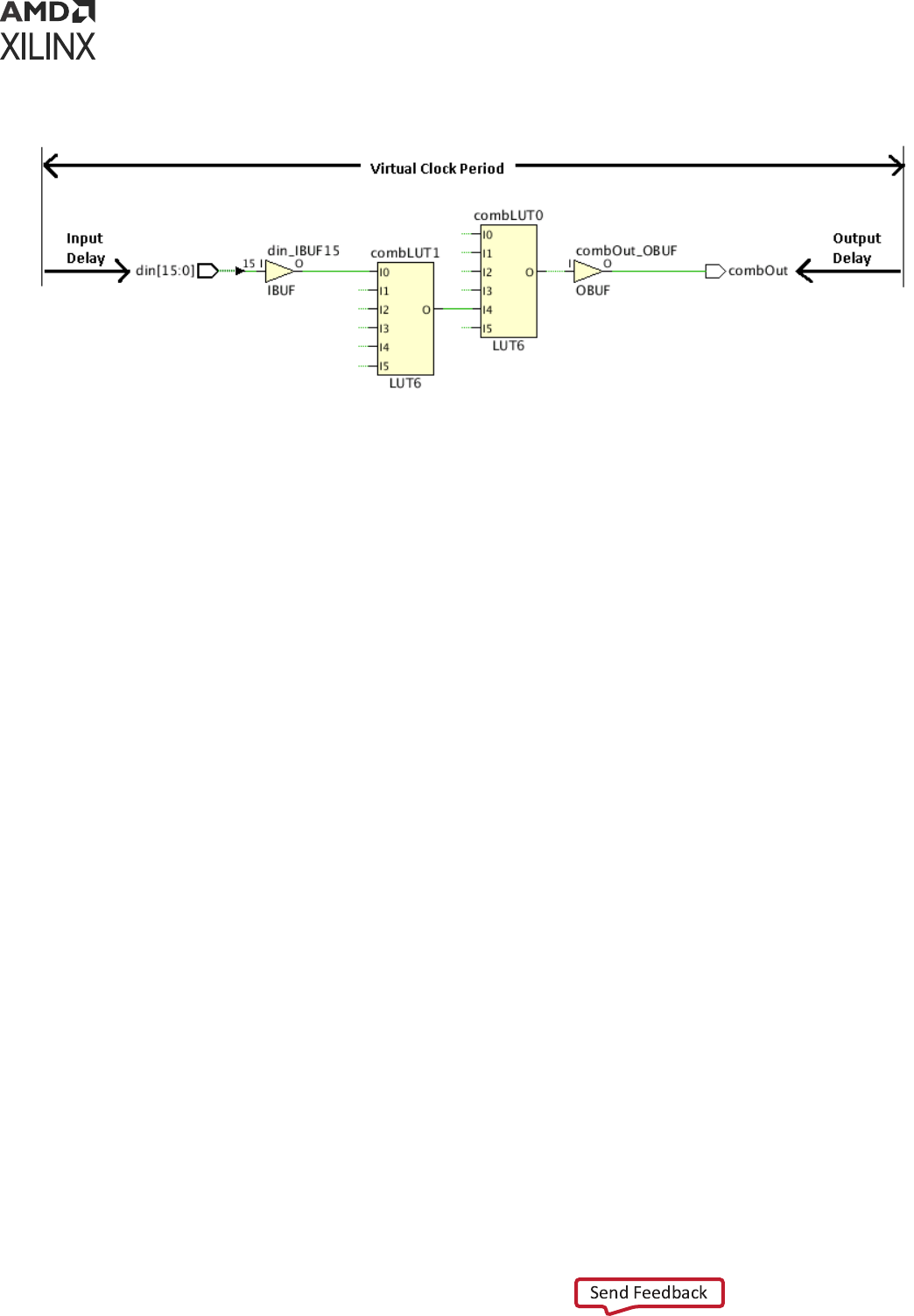
Figure 23: Combinational Path Schematics and Delay Constraints
The nal combinaonal path delay constraints are:
• For setup analysis:
virtual clock period - max input delay - max output delay
• For hold analysis:
0 - min output delay - min input delay
The virtual clock period must be modied so that it is greater than the largest combinaonal
delay constraint across all constrained combinaonal paths. The following gure shows the delay
entries needed per input/output ports pair.
Chapter 2: Constraints Methodology
UG903 (v2022.1) June 1, 2022 www.xilinx.com
Using Constraints 40
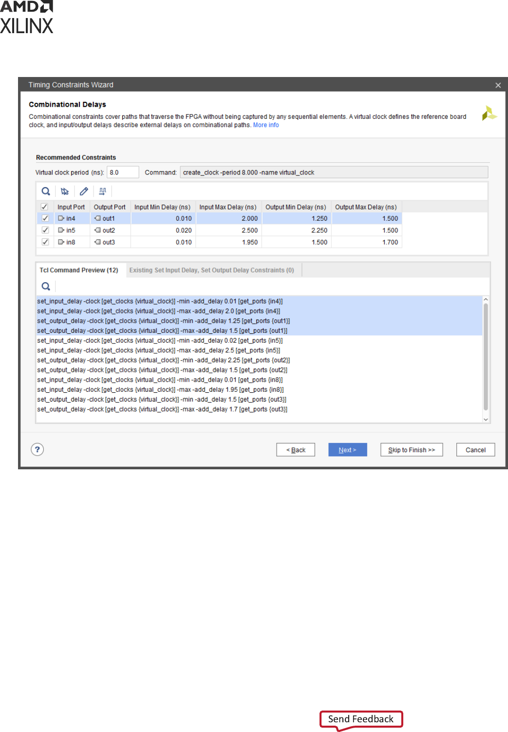
Figure 24: Recommended Combination Paths Constraints
None of the input and output delay constraints override exisng ones. If a given port has
mulple delay constraints with respect to the same clock, the smallest value of all constraints is
used by the Vivado Timing analysis feature during hold analysis, and the largest one during setup
analysis.
Aer all delay entries have been lled, you can click Next to proceed to the next step.
Note: Alternavely, you can constrain combinaonal paths using the set_max_delay and
set_min_delay commands outside the Timing Constraints wizard.
Physically Exclusive Clock Groups
Physically exclusive clocks are clocks that are dened on the same source point and propagate on
the same clock tree. The following gure shows an example where two primary clocks are
dened on the same input port.
Chapter 2: Constraints Methodology
UG903 (v2022.1) June 1, 2022 www.xilinx.com
Using Constraints 41
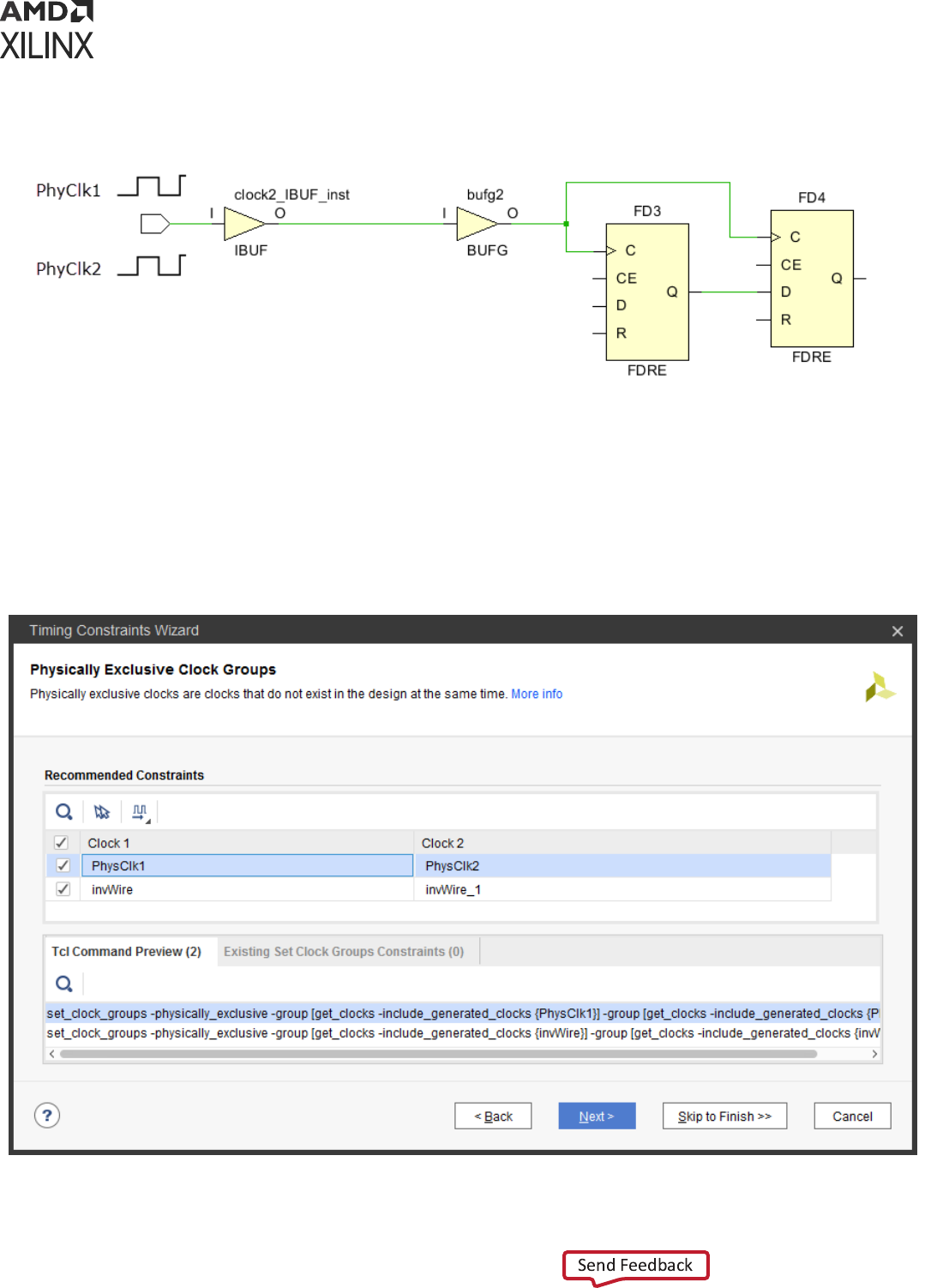
Figure 25: Example of a Design with Physically Exclusive Clocks
While their overlap is convenient for ming several applicaon modes with one design and
constraint database, these clocks and their children generated clocks should never be med
together. The Timing Constraints wizard idenes such clocks and recommends a clock groups
constraint to prevent unnecessary ming analysis on the clock domain crossing paths, as shown
in the following gure.
Figure 26: Example of a Design with Clock Groups Constraint
Chapter 2: Constraints Methodology
UG903 (v2022.1) June 1, 2022 www.xilinx.com
Using Constraints 42
Logically Exclusive Clock Groups with No Interaction
Logically exclusive clocks are clocks that are dened on dierent source points but share part of
their clock tree due to a mulplexer or other combinaonal logic. The Timing Constraints wizard
idenes such clocks and recommends a clock groups constraint directly on them when they do
not have ming paths between each other except for the logic connected to their shared clock
tree. The following gure shows an example of two clocks, clkA and clkB, which are dened on
dierent input ports and start overlapping on the output of a BUFGMUX.
Figure 27: Example of Logically Exclusive Clocks with No Interaction
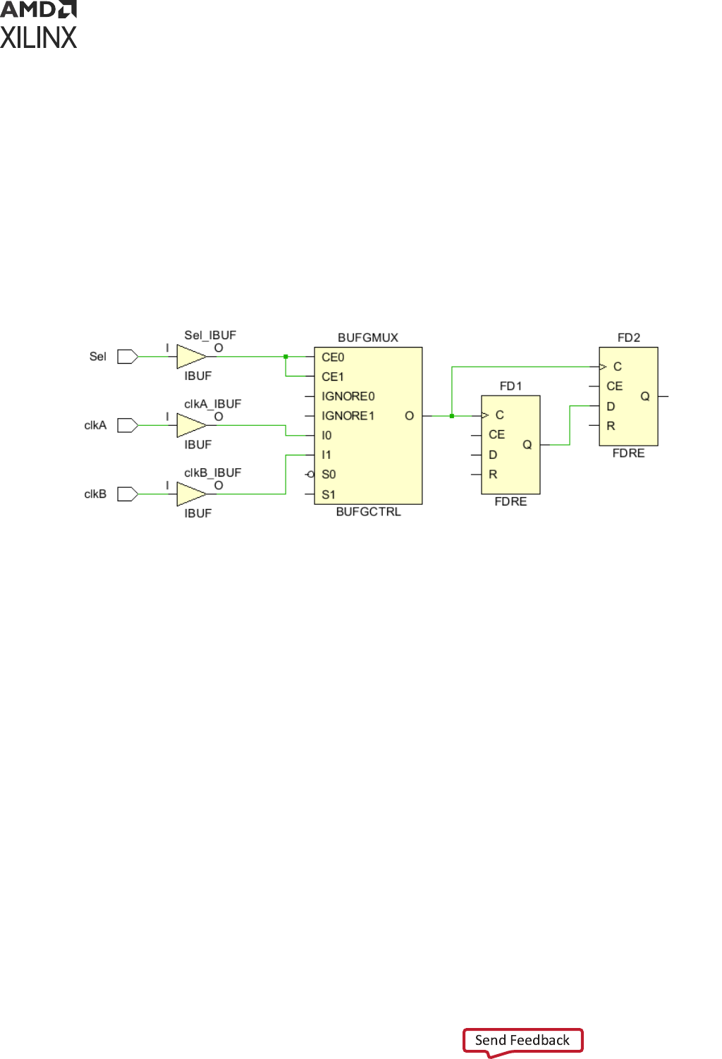
Logically Exclusive Clock Groups with Interaction
The Timing Constraints wizard idenes logically exclusive clocks that have ming paths
between each other elsewhere than just on the logic connected to the shared clock tree. The
following gure shows an example where clkA and clkB have a shared clock tree poron, and
also have a ming path from the shared clock tree to clkA only.
Chapter 2: Constraints Methodology
UG903 (v2022.1) June 1, 2022 www.xilinx.com
Using Constraints 43
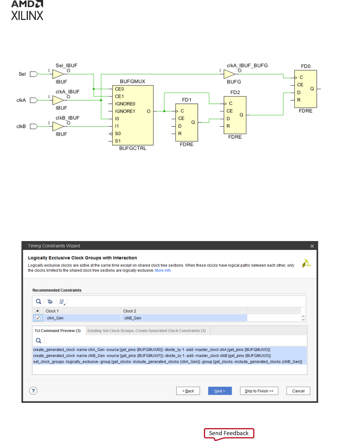
Figure 28: Example of a Design with Logically Exclusive Clocks with Interaction
Because only the clock domain crossing paths of the shared clock tree must be ignored, the
wizard recommends to create generated clocks that are copies of clkA and clkB but that only
exist on the shared clock tree. The clock groups constraint is applied to the generated clocks
only, so that the paths outside the logic of the shared clock tree can sll be normally med. The
following gure illustrates the wizard recommended constraints for the example above.
Figure 29: Recommended Constraints for Logically Exclusive Clocks with Interaction
Chapter 2: Constraints Methodology
UG903 (v2022.1) June 1, 2022 www.xilinx.com
Using Constraints 44

Asynchronous Clock Domain Crossings
The Timing Constraints wizard analyzes the topology of clock domain crossing (CDC) paths
between asynchronous clocks and recommends clock groups or false path constraints whenever
it is safe to do so.
Asynchronous clocks are clocks with no known phase relaonship, which typically happens when
they do not share the same primary clock or do not have a common period. For this reason, slack
computaon on asynchronous CDC paths is not accurate and cannot be trusted. Due to
potenally large skew between asynchronous clocks, the ming quality-of-result can be heavily
impacted and prevent proper ming closure if any of the asynchronous CDC paths is med. You
are responsible for adding ming excepons on these paths, such as set_clock_groups,
set_false_path, or set_max_delay -datapath_only to either completely ignore ming
analysis or just ignore the clock skew and uncertainty. Also, the design must implement proper
CDC circuitry to prevent metastability.
In the Vivado Design Suite, the wizard only idenes ip-op-based synchronizers for
synchronous data and asynchronous reset. For an example of such synchronizers, see the Vivado
Design Suite User Guide: Design Analysis and Closure Techniques (UG906).
The following gure shows an example of the recommended and non-recommended constraints
tables.
Chapter 2: Constraints Methodology
UG903 (v2022.1) June 1, 2022 www.xilinx.com
Using Constraints 45
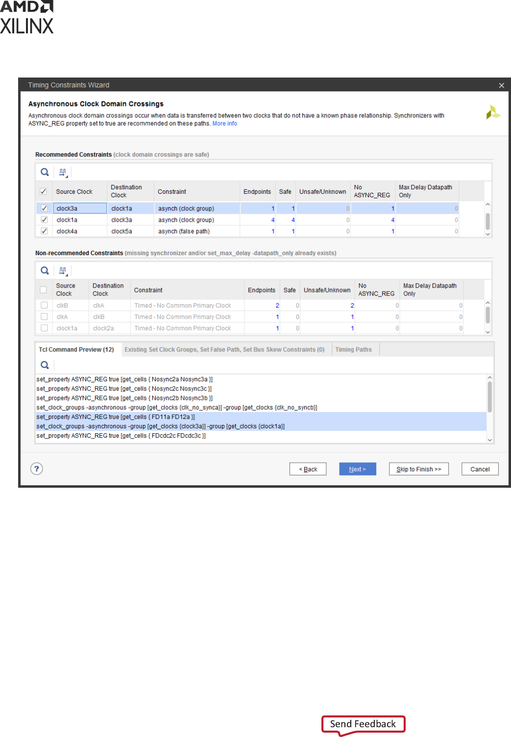
Figure 30: Example of Recommended and Non-Recommended Constraints Tables
The columns in both tables display the following informaon:
• Source Clock: This is the clock of the CDC paths start points idened by the wizard.
• Desnaon Clock: This is the clock of the CDC paths endpoints idened by the wizard.
• Constraint: This column shows either the dominant ming excepon or the characteriscs of
the clock relaonship when there is no excepon.
• In the Recommended Constraints table, the wizard ancipates that the constraints will be
created and displays the new constraint:
○ asynch (clock groups) for the cases where it is safe to ignore ming in both direcons, in
which case a set_clock_groups constraint is created
Chapter 2: Constraints Methodology
UG903 (v2022.1) June 1, 2022 www.xilinx.com
Using Constraints 46

○ asynch (false path) when it is only safe to ignore the paths in one direcon, in which
case a set_false_path constraint is created
• In the Non-recommended Constraints table, the Timing Constraints wizard displays how
the CDC paths are med before eventually applying a clock group or false path excepon:
○ Timed - No Common Primary Clock
○ Timed - No Common Period
○ MaxDelay DataPath for the case where at least 1 path is covered by a set_max_delay
-datapath_only constraint and all other paths are covered by false path constraints
• Endpoints: The number of CDC path endpoints idened by the wizard.
• Synchronized (with ASYNC_REG): The number of endpoints properly synchronized, with the
ASYNC_REG property set to true on all synchronizer ip-ops.
• Synchronizer without ASYNC_REG: The number of synchronizers where at least one ip-op
does not have the ASYNC_REG property set to true.
• Unknown: The number of CDC path endpoints where the wizard did not nd a synchronizer.
• Max Delay Datapath Only: The number of CDC path endpoints that are constrained with a
set_max_delay -datapath_only constraint.
The table entries contain cross-probing links whenever applicable. When you click on a number,
the corresponding CDC paths are listed in the Paths tab at the boom of the window. You can
select one or several CDC paths and click on the Schemac (F4) buon to display the logic of the
path(s) in the main Vivado IDE window.
Recommended Asynchronous Clock Groups Constraints
The Timing Constraints wizard recommends a set_clock_groups -asynchronous
constraint between two clocks when the following condions are present:
• All paths have synchronizers in both direcons.
• No path is covered by a set_max_delay -datapath_only in either direcon
(set_clock_groups has higher precedence and overrides any exisng set_max_delay).
Non-Recommended Asynchronous Clock Groups Constraints
The Timing Constraints wizard provides a table with constraints that are not enabled by default
because they are not recommended for one of the following reasons:
• At least one path is missing a synchronizer in either direcon.
• At least one path is covered by set_max_delay -datapath_only in either direcon.
You can decide to acvate any of these constraints when working on an early version of the
design, and then revisit the CDC paths and their constraints later when nalizing your design.
Chapter 2: Constraints Methodology
UG903 (v2022.1) June 1, 2022 www.xilinx.com
Using Constraints 47

CDC Synchronizers and ASYNC_REG Property
Xilinx recommends that all synchronizer ip-ops have their ASYNC_REG property set to true in
order to preserve the synchronizer cells through any logic opmizaon during synthesis and
implementaon, and to opmize their placement for best Mean Time Between Failures (MTBF)
stascs. For any clock group constraints that are enabled in both tables (either by default or by
the user), the wizard sets to true any missing ASYNC_REG property.
Refer to the Vivado Design Suite Properes Reference Guide (UG912) for detailed informaon
about the ASYNC_REG property.
Completing the CDC Analysis and Constraints
The Timing Constraints wizard does not recognize some valid CDC topologies that are not based
on simple synchronizers. The report_cdc command provides a powerful and more comprehensive
view of the CDC paths that need structural correcon in order to become safe. Refer to the
Vivado Design Suite User Guide: Design Analysis and Closure Techniques (UG906) for detailed
informaon about report_cdc.
For the cases where the wizard does not recommend a constraint due to the presence of some
set_max_delay -datapath_only, the other CDC paths that are normally med must be
reviewed individually and possibly ignored by addional false path constraints. The creaon of
point-to-point false path constraints must be done in the XDC le, in the Tcl Console, or in the
Timing Constraints window aer exing the wizard.
Constraints Summary
The nal page of the Timing Constraints wizard summarizes the new constraints that will be
applied and saved at the end of the Target XDC le when you click Finish. Click each hyperlink to
see the details of the constraints. The following gure below shows an example of the
Constraints Summary page.
Chapter 2: Constraints Methodology
UG903 (v2022.1) June 1, 2022 www.xilinx.com
Using Constraints 48
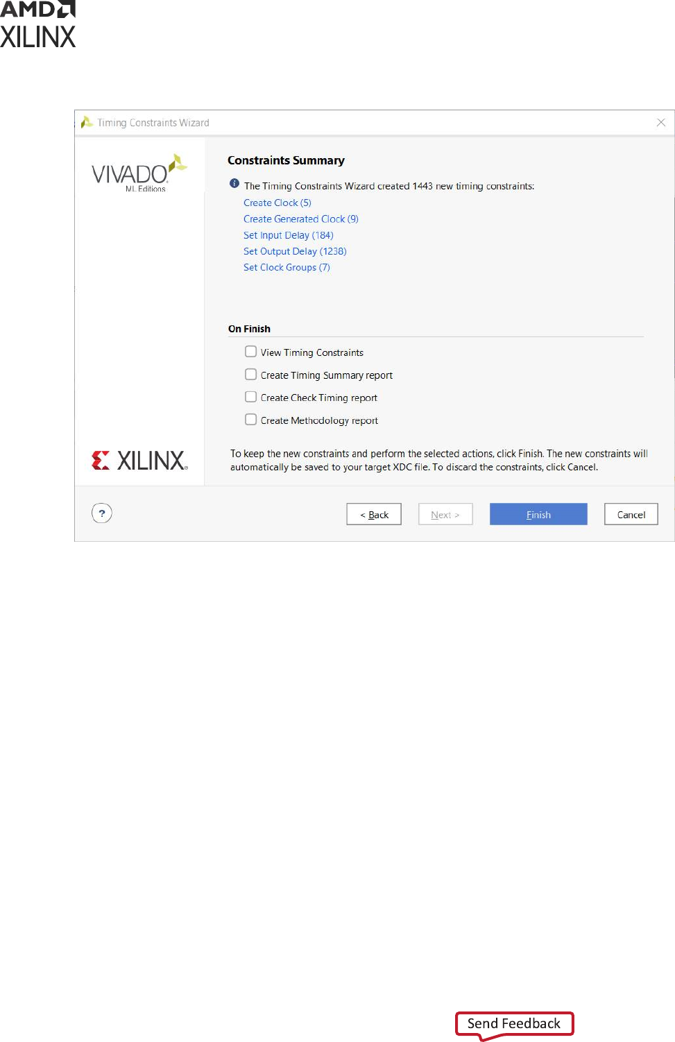
Figure 31: Example of Constraints Summary Page
Timing Constraints Window
The Timing Constraints window is available for Synthesized and Implemented designs only. For
elaborated design constraints, you must use and edit XDC les directly. For more informaon,
see Creang Synthesis Constraints.
You can open the Timing Constraints window using one of the following three opons, as shown
in the following gure:
• Select Window → Timing Constraints.
• In the Synthesis secon of the Flow Navigator panel, select Synthesized Design → Edit Timing
Constraints.
• In the Implementaon secon of the Flow Navigator panel, select Implemented Design → Edit
Timing Constraints.
Chapter 2: Constraints Methodology
UG903 (v2022.1) June 1, 2022 www.xilinx.com
Using Constraints 49
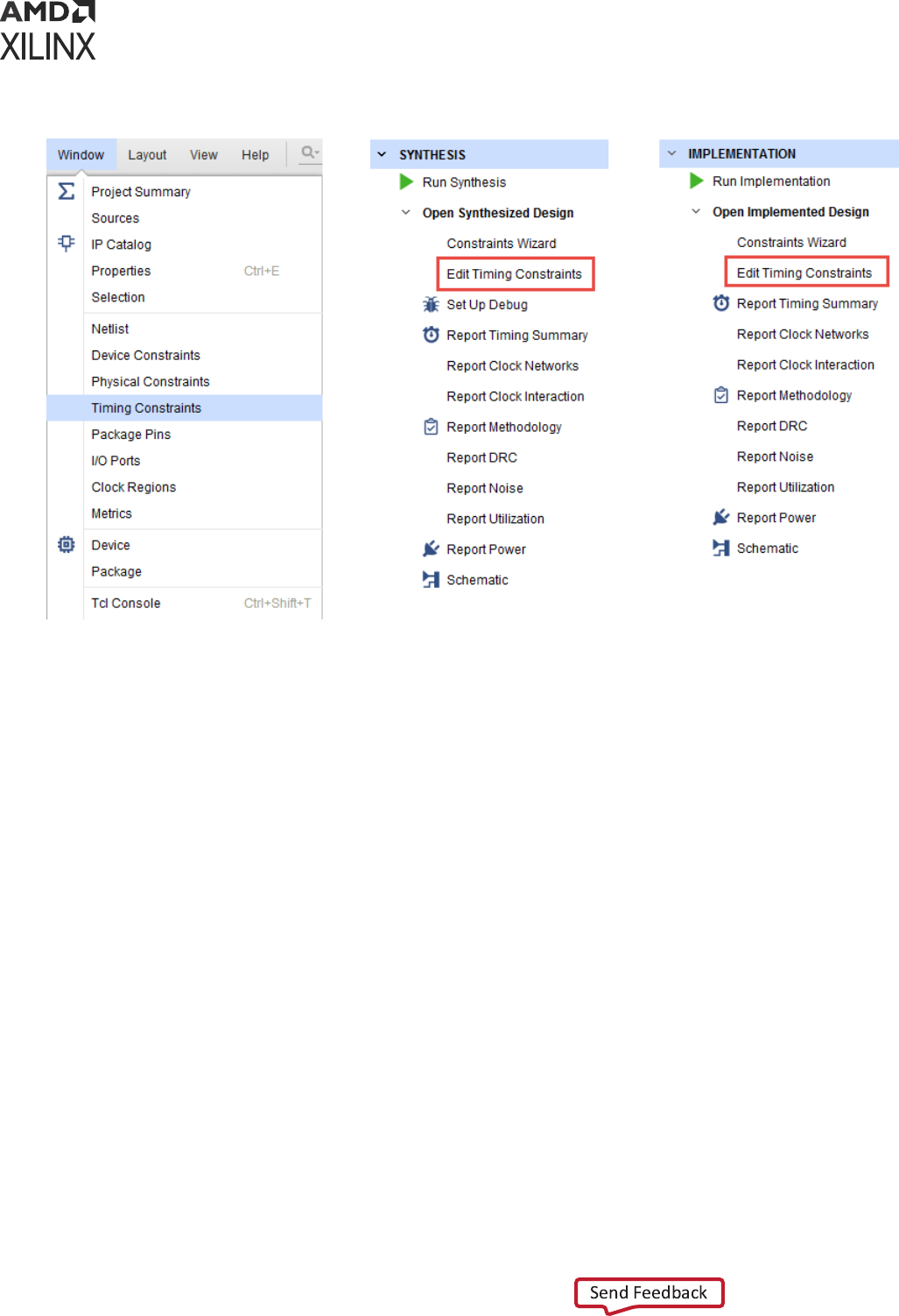
Figure 32: Multiple Methods for Opening the Timing Constraints Window
The Timing Constraints window displays the ming constraints in memory, in either the same
sequence as in the XDC les and Tcl scripts, or the same sequence in which you entered them in
the Tcl Console.
Chapter 2: Constraints Methodology
UG903 (v2022.1) June 1, 2022 www.xilinx.com
Using Constraints 50
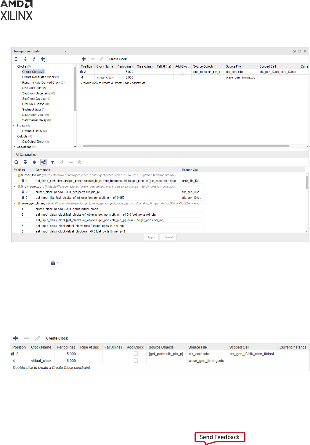
Figure 33: Timing Constraints Window
Some of the constraints cannot be edited from this window. They are marked with the XDC No
Edit icon .
Timing Constraints Spreadsheet
The ming constraints spreadsheet displays the details of all exisng constraints of a specic
type. Use the ming constraints spreadsheet to review and edit constraint opons.
Figure 34: Timing Constraints Spreadsheet
The two last columns of the panel show:
• Source File: The name of the XDC le or Tcl script the constraint comes from.
Chapter 2: Constraints Methodology
UG903 (v2022.1) June 1, 2022 www.xilinx.com
Using Constraints 51

• Scoped Cell: The name of the current instance when the constraint was applied. This name
usually corresponds to an IP instance which is delivered with dedicated constraints. For more
informaon, see Constraints Scoping.
A new constraint of the selected type can be created by double clicking the last line of the
spreadsheet. The corresponding constraint creaon dialog opens and lets you ll in the details of
the new constraint. Click OK to apply the constraint in memory and close the window. A new
line in the spreadsheet shows the new constraint informaon.
You can edit any exisng constraint by modifying the values directly in the spreadsheet. Aer
you have nished eding, click Apply to apply the modied constraints in memory.
IMPORTANT! Applying a new or modied constraint does not save it in the XDC le. You must click Save
Constraints to save it.
IMPORTANT! IP constraints cannot be edited or deleted. In order to modify a constraint delivered with an
IP, you must disable the corresponding IP XDC le, copy the constraint to your XDC le, and edit the
constraint as desired.
Constraints Creation, Grouped by Category
When you select a constraint type, the corresponding spreadsheet appears on the right sub-
window panel. This allows you to view all the constraints of the same type that have already
been created.
Chapter 2: Constraints Methodology
UG903 (v2022.1) June 1, 2022 www.xilinx.com
Using Constraints 52
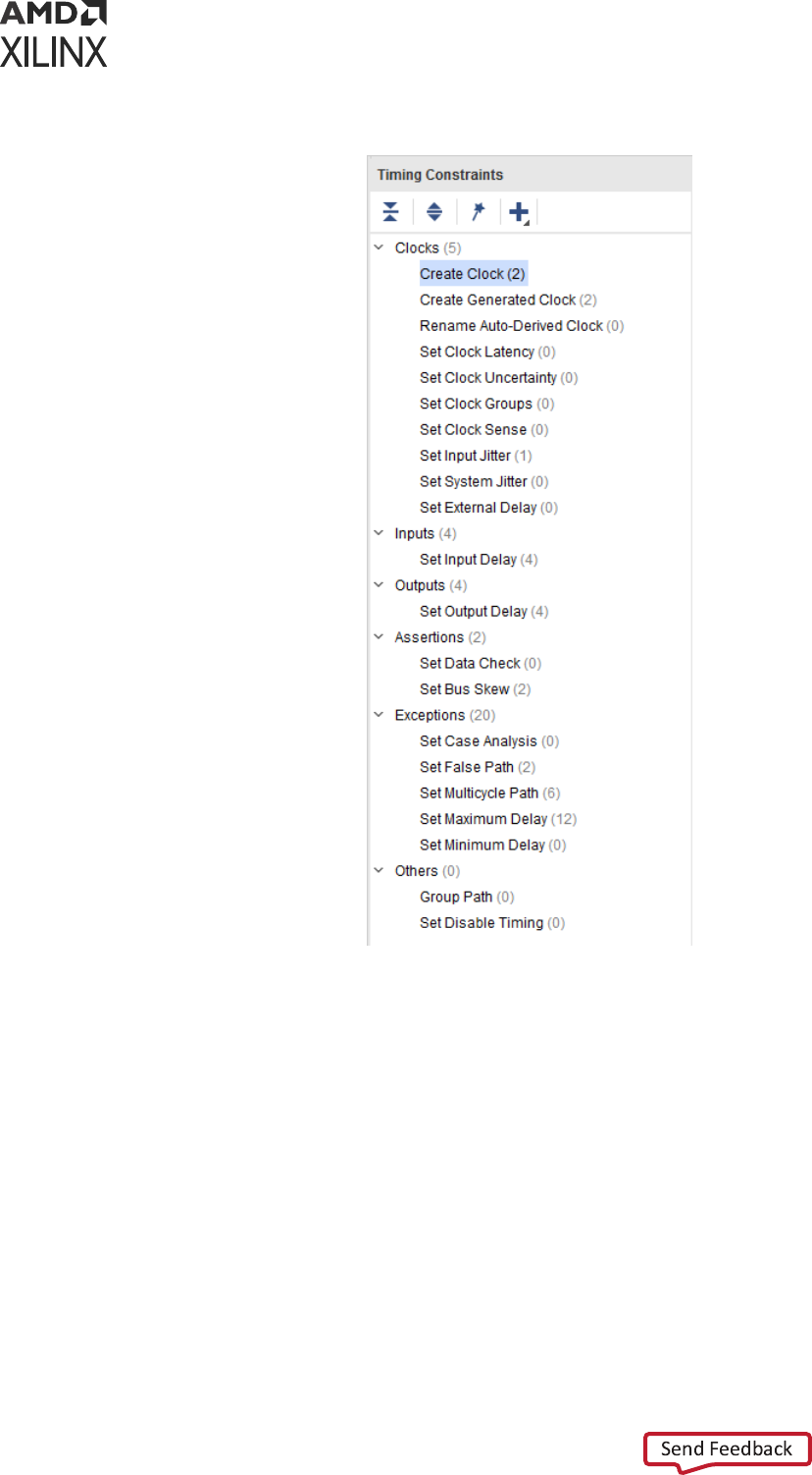
Figure 35: Timing Constraints Categories
To create a new constraint, double click the name of the target constraint. A dialog box allows
you to specify the value for each opon. When you click OK, the tool does the following:
1. Validates the syntax.
2. Applies the syntax to the memory.
3. Adds the new constraint at the end of the spreadsheet.
4. Adds the new constraint at the end of your complete list of constraints.
Chapter 2: Constraints Methodology
UG903 (v2022.1) June 1, 2022 www.xilinx.com
Using Constraints 53
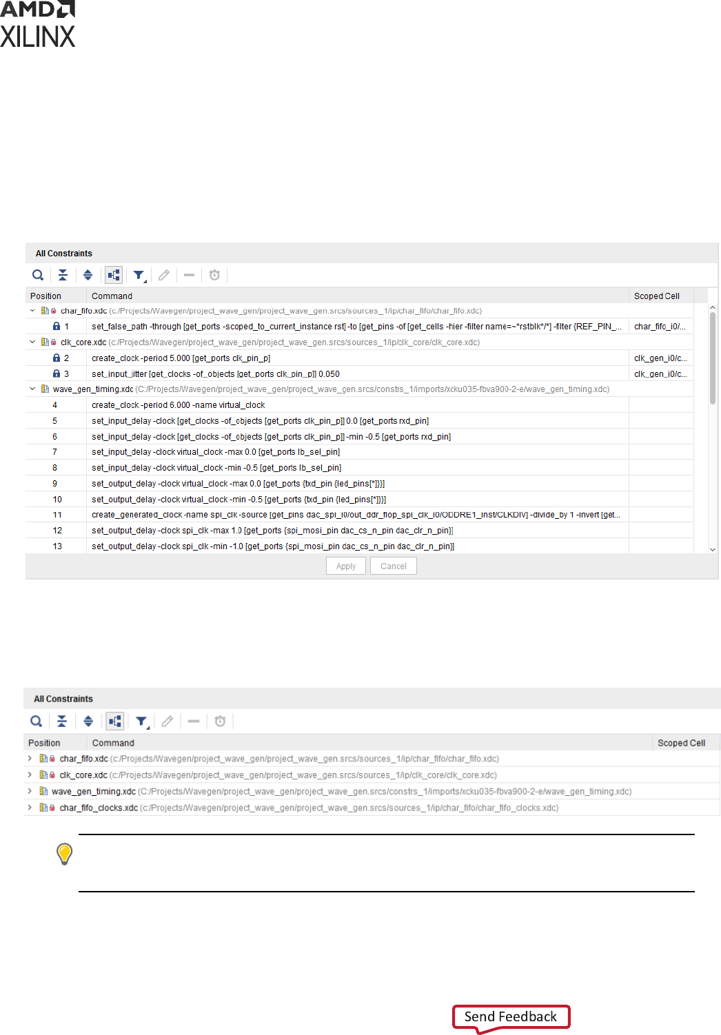
All Constraints
The boom of the window displays the complete list of constraints loaded in memory, in the
same sequence as they were applied. The constraints are grouped in accordance with the XDC
le or the Tcl script from which they originated. When an XDC le is scoped to a parcular
hierarchical cell, the cell name is displayed next to the le name.
Figure 36: Timing Constraints All Constraints List (Example One)
You can expand and collapse the constraints for each associated source
le, or completely by
clicking the two corresponding buons on the le side of the panel.
Figure 37: Timing Constraints All Constraints List (Example Two)
TIP:
The collapsed view provides a compact overview of which constraints le are loaded in memory, and
where the scoping mechanism is used. The same informaon is available through the
report_compile_order -constraints
command.
Chapter 2: Constraints Methodology
UG903 (v2022.1) June 1, 2022 www.xilinx.com
Using Constraints 54
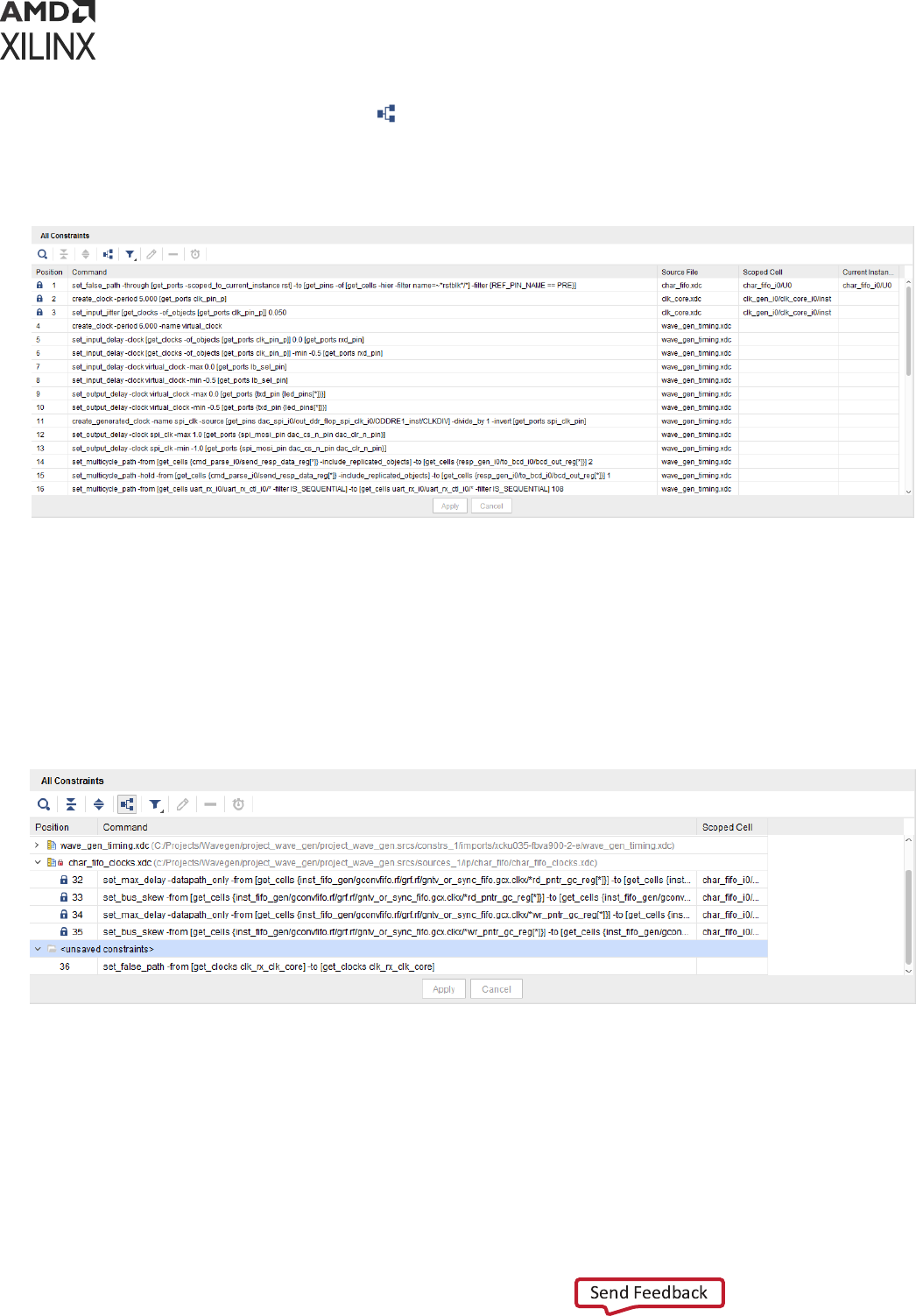
De-select the Group by Source icon to switch the view to a table in which the source
constraint le and the scoped cell informaon appears in the two right columns.
Figure 38: Timing Constraints All Constraints List (Example Three)
• To delete a constraint, select it and click X.
• To edit a constraint that is not read-only, use the spreadsheet view. Aer your changes have
been registered by the tool, you must click Apply to refresh the constraints in memory.
• To add new constraints, use the dialog boxes as previously described, or type the constraints
in the Tcl Console. The new constraint appears at the end of the list in a group named
<unsaved_constraints>.
Figure 39: Timing Constraints All Constraints List (Example Four)
When saving the constraints, the new constraints are saved at the end of the XDC le marked as
target. If there is no target XDC le in the constraint set associated with the design in memory, or
if there is only a Tcl script in the constraint set, you are prompted to specify where to save the
constraints.
Regularly save your constraints. Click Save, or select File → Constraints → Save.
Chapter 2: Constraints Methodology
UG903 (v2022.1) June 1, 2022 www.xilinx.com
Using Constraints 55
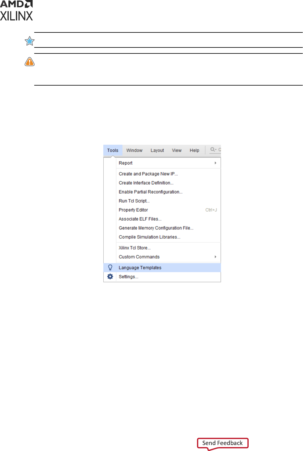
IMPORTANT! New and modied constraints cannot be saved back to a Tcl script.
CAUTION! Do not enter new constraints in the Tcl Console if any constraints in the Timing Constraints
window have not yet been applied. The nal constraints order in the editor can become dierent from the
constraints order in memory. In order to avoid any confusion, you must re-apply all constraints each me
you edit an exisng constraint.
XDC Templates
You can access XDC templates by selecng Tools → Language Templates.
Figure 40: XDC Templates
XDC Template Contents
The XDC templates include:
• The most common ming constraints, such as clock denions, jier, input/output delay, and
excepons
• Physical constraints
• Conguraon constraints
Using XDC Templates
To use an XDC template:
1. Select the template you want to use.
Chapter 2: Constraints Methodology
UG903 (v2022.1) June 1, 2022 www.xilinx.com
Using Constraints 56
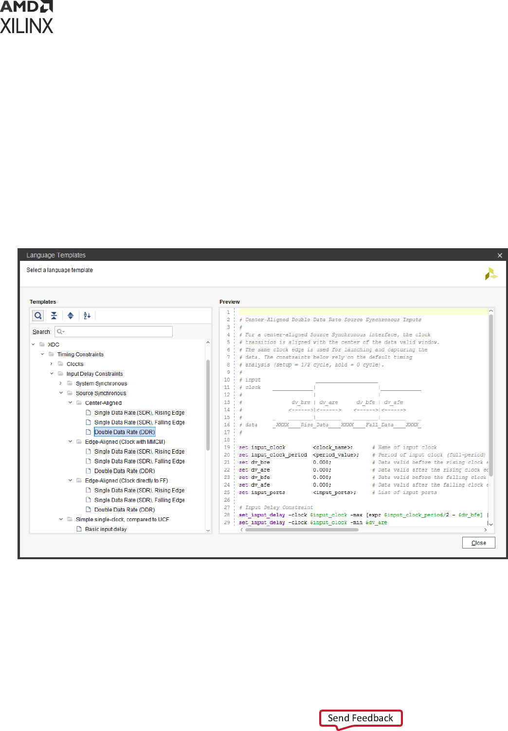
2. Copy the text displayed in the Preview window.
3. Paste the text in your XDC le.
4. Replace the generic strings with actual names from your design or with appropriate values.
Advanced XDC Templates
Some advanced templates such as System Synchronous and Source Synchronous I/O delay
constraints require you to set some Tcl variables to capture the design requirements. The Tcl
variables are used in the actual set_input_delay and set_output_delay constraints.
You must verify that all necessary values have been lled instead of using the default values.
Figure 41: I/O Delay Constraint Templates
Chapter 2: Constraints Methodology
UG903 (v2022.1) June 1, 2022 www.xilinx.com
Using Constraints 57

Creating Synthesis Constraints
The Vivado Synthesis transforms the RTL descripon of your design into a technology mapped
netlist. This process happens in several steps, and includes a number of ming-driven
opmizaons.
Xilinx FPGAs include many logic features that can be used in many dierent ways. Your
constraints are needed to guide the synthesis engine towards a soluon that meets all the design
requirements at the end of implementaon.
There are four categories of constraints for the Vivado IDE synthesis:
• RTL Aributes
• Timing Constraints
• Physical and Conguraon Constraints
• Elaborated Design Constraints
RTL Attributes
RTL aributes must be wrien in the RTL les. They usually choose the mapping style of certain
part of the logic, as well as preserving certain registers and nets, or controlling the design
hierarchy in the nal netlist.
For more informaon, see this link in the Vivado Design Suite User Guide: Synthesis (UG901).
Note: The DONT_TOUCH aribute does not obey the properes of USED_IN_SYNTHESIS and
USED_IN_IMPLEMENTATION. If you use DONT_TOUCH properes in the synthesis XDC, it is propagated
to implementaon regardless of the value of USED_IN_IMPLEMENTATION.
For more informaon about USED_IN_SYNTHESIS and USED_IN_IMPLEMENTATION, Refer to Synthesis
and Implementaon Constraint Files.
DONT_TOUCH aribute example:
set_property DONT_TOUCH true [get_cells fsm_reg]
Timing Constraints
Timing constraints must be passed to the synthesis engine by means of one or more XDC les.
Only the following constraints related to setup analysis have any real impact on synthesis results:
• create_clock
• create_generated_clock
Chapter 2: Constraints Methodology
UG903 (v2022.1) June 1, 2022 www.xilinx.com
Using Constraints 58
• set_input_delay
• set_output_delay
• set_clock_groups
• set_false_path
• set_max_delay
• set_multicycle_path
Physical and Configuration Constraints
Physical and conguraon constraints are ignored by the synthesis algorithms.
Elaborated Design Constraints
RECOMMENDED: When you create the rst version of your synthesis XDC, use simple ming constraints
to describe the high-level design requirements.
At this point in the ow, the net delay modeling is sll not very accurate. The main goal is to
obtain a synthesized netlist which meets ming, or fail by a small amount, before starng
implementaon. In many cases, you will have to go through several XDC and RTL modicaon
iteraons before you can reach this state.
The RTL-based XDC creaon iteraon is shown in the following gure. It is based on the
ulizaon of the Elaborated design to nd the object names in your design that you want to
constrain for synthesis.
You must use the Tcl Console to validate the syntax of the XDC commands before saving them in
the XDC les. With the elaborated design, you can create constraints, query clocks, and query
design objects, but you cannot run any ming report command.
Chapter 2: Constraints Methodology
UG903 (v2022.1) June 1, 2022 www.xilinx.com
Using Constraints 59
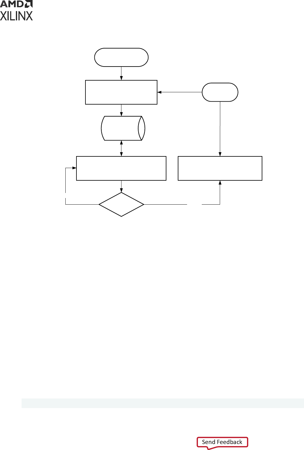
Figure 42: Creating Constraints with the Elaborated Design
RTL source files
Vivado
Database
(elaborated)
Query names in your design
Validate XDC syntax in Tcl Console
Syntax Clean?
Copy/paste good XDC commands
from Tcl Console to XDC files
Open (or reload)
Elaborated Design
XDC files
YES
NO
X12982
Design objects that are safe to use when wring constraints for synthesis are:
• Top level ports
• Manually instanated primives (cells and pins)
Some RTL names are modied or lost during the creaon of the elaborated design. Following are
the most common cases:
• Single-Bit Register Names
• Mul-Bit Register Names
• Absorbed Registers and Nets
• Hierarchical Names
Single-Bit Register Names
By default, the register name is based on the signal name in the RTL, plus the _reg sux.
For example, for a signal dened as follows in VHDL and Verilog, the instance name generated
during the elaboraon is wbDataForInputReg_reg:
VHDL: signal wbDataForInputReg : std_logic; Verilog: reg wbDataForInputReg;
Chapter 2: Constraints Methodology
UG903 (v2022.1) June 1, 2022 www.xilinx.com
Using Constraints 60
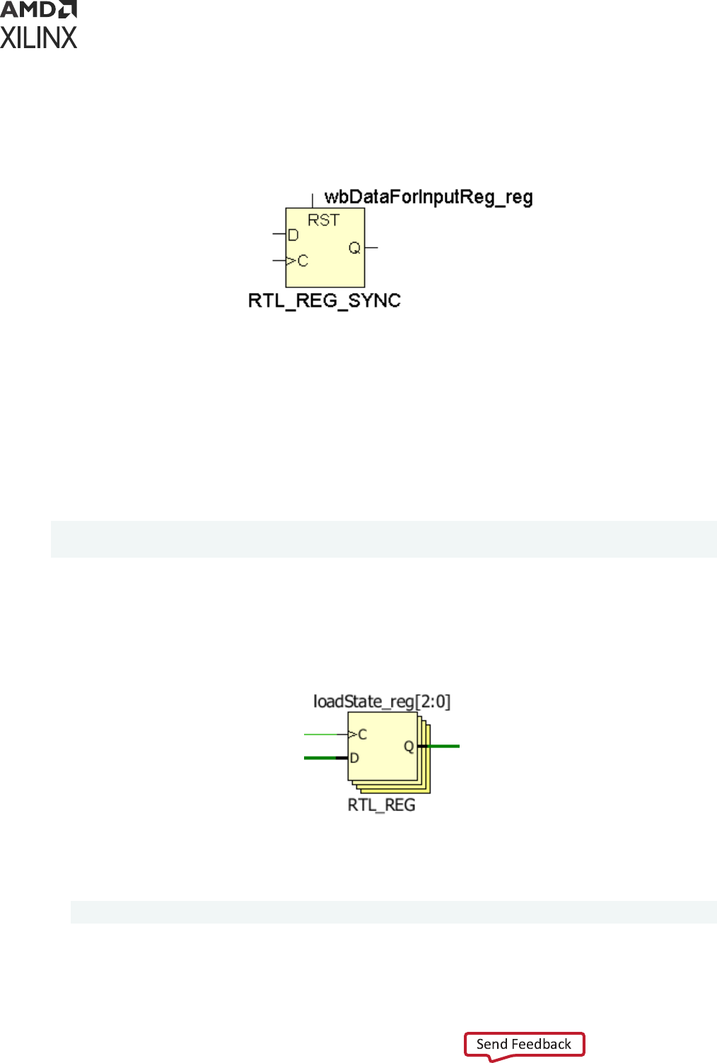
The following gure shows the schemac of the register, and its pins. It is possible to dene a
constraint on the register instance or its pins.
Figure 43: Single-Bit Register in Elaborated Design
Multi-Bit Register Names
By default, the register name is based on the signal name in the RTL, plus the _reg sux. You
can only query and constrain individual bits of the mul-bit register in your XDC commands.
For example, for a signal dened as follows in VHDL and Verilog, the instance names generated
during the elaboraon are loadState_reg[0], loadState_reg[1], and
loadState_reg[2]:
VHDL: signal loadState: std_logic_vector(2 downto 0); Verilog: reg [2:0]
loadState;
The following gure shows the schemac of the register. The mul-bit register appears as a
vector of single-bit registers. The vector is represented in a compact way whenever possible in
the schemacs. Each individual bit can also be displayed separately.
Figure 44: Multi-Bit Register in Elaborated Design
You can only constrain each register individually or as a group by using the following paerns:
• Register bit 0 only
loadState_reg[0]
Chapter 2: Constraints Methodology
UG903 (v2022.1) June 1, 2022 www.xilinx.com
Using Constraints 61

• All register bits
loadState_reg[*]
IMPORTANT! You cannot query the mul-bit register, or more generally any mul-bit instance, by using
the paern
loadState_reg[2:0]
.
Because the names above also correspond to the names in the post-synthesis netlist, any
constraint based on them will most probably work for implementaon as well.
Absorbed Registers and Nets
Some registers or nets in the RTL sources can disappear in the elaborated design (or synthesized
design) for various reasons. For example, memory block, DSP or shi register inference requires
absorbing several design objects into one resource. Instead of using these objects to dene
constraints, try to nd other connected registers or nets that you can use.
Hierarchical Names
Unless you plan to force Vivado synthesis to keep the complete hierarchy of your design, some
or all levels of the hierarchy can be aened during synthesis. For more informaon, see the -
flatten_hierarchy informaon at this link in the Vivado Design Suite User Guide: Synthesis
(UG901).
RECOMMENDED:
Use fully resolved hierarchical names in your synthesis constraints where all the
hierarchical levels are explicitly wrien ("/" character) instead of using implicit matching ("*"character).
They are more likely to be matching the nal netlist names regardless of the hierarchy transformaons.
For example, consider the following register located in a sub-level of the design. Elaborated
Design Example:
inst_A/inst_B/control_reg
During synthesis (assuming no special opmizaon is performed on this register), you can get
either at or hierarchical name depending on the tool opons or the design structure.
Instance name in a at netlist:
inst_A/inst_B/control_reg (F)
Instance name in a hierarchical netlist:
inst_A/inst_B/control_reg (H)
Chapter 2: Constraints Methodology
UG903 (v2022.1) June 1, 2022 www.xilinx.com
Using Constraints 62
There is no obvious dierence because the / character is also used to mark aened hierarchy
levels. You will noce the dierence when querying the object in memory. The following
commands will return the netlist object for F but not H:
% get_cells -hierarchical *inst_B/control_reg
% get_cells inst_A*control_reg
In order to avoid problems related to hierarchical names, Xilinx recommends that you do the
following:
• Use get_* commands without the -hierarchical opon.
• Mark explicitly with the forward-slash (/) character all the levels of hierarchy as they show in
the elaborated design view.
Examples without the -hierarchical opon:
• This opon works for both at and hierarchical netlists:
% get_cells inst_A/inst_B/*_reg
% get_cells inst_*/inst_B/control_reg
• Another opon is:
% get_cells -hier -filter {NAME =~ inst_A/inst_B/*_reg}
% get_cells -hier -filter {NAME =~ inst_*/inst_B/control_reg}
CAUTION!
(1) Do not aach constraints to hierarchical pins during synthesis for the same reason as
explained above for hierarchical cells. (2) Do not aach constraints to nets connecng combinatorial logic
operators. They will likely be merged into a LUT and disappear from the netlist.
RECOMMENDED: Regularly save your XDC les aer eding, and reload the Elaborated design in order
to make sure the constraints in memory and the constraints in the XDC les are the same. Aer running
synthesis, load the synthesized design with the same synthesis XDC in memory, and run ming analysis by
using the ming summary report.
Some pre-synthesis constraints might no longer apply properly because of the
transformaons
performed by synthesis on the design. To resolve these problems, do the following:
1. Find the new XDC syntax that applies to the synthesized netlist.
2. Save the constraints in a new XDC le to be used during implementaon only.
3. Move the synthesis constraints that can no longer be applied to a separate XDC le that will
be used for synthesis only.
Chapter 2: Constraints Methodology
UG903 (v2022.1) June 1, 2022 www.xilinx.com
Using Constraints 63

Creating Implementation Constraints
Aer you have a synthesized netlist, you can load it into memory together with the XDC les or
Tcl scripts enabled for implementaon. You must review the messages issued by the tool when
loading the XDC in order to verify and correct any constraint that cannot be applied.
In some cases, the object names in the synthesized netlist are dierent from the names in the
elaborated design. If this is the case, you must recreate some constraints with the corrected
names, and save them in an implementaon-only XDC le.
Aer the tool can properly load all the XDC les, you can run ming analysis in order to:
• Add missing constraints, such as input and output delay.
• Add ming excepons, such as false paths, mulcycle paths, and min/max delay constraints.
• Idenfy large violaons due to long paths in the design and correct the RTL descripon.
You can use the same base constraints as during synthesis, and create a second XDC le to store
all new constraints specic to implementaon. You can choose to save physical and conguraon
constraints in a separate XDC le.
Note: In project mode, opening a synthesized design results in linking the netlist(s) from the post-synthesis
DCP(s) to build the full top-level hierarchical netlist. All XDC constraints marked for implementaon are
also automacally loaded. This enables you to verify the implementaon constraints on the full
synthesized design. This means that if the implementaon constraints are modied, the opened
synthesized design goes out of date, not the synthesized run. The GUI shows a small banner and provides
the opon to reload the design.
The netlist-based XDC iteraon is shown in Figure 45.
Constraints and Object Queries
Design constraints that contain object queries based on some physical informaon must not rely
on physical constraints entered by Vivado P&R commands, and only rely on physical constraints
that the user enters, else such constraints will appear invalid when reloading a post-
implementaon DCP. This requirement comes from the DCP load sequence where the netlist is
read rst, then the constraints and physical database last. Instead of using physical informaon,
you should modify the query to depend on other design objects properes (NAME,
REF_NAME, ...).
Example of non-recommended constraint relying on placement informaon (property LOC):
set_false_path -from [get_cells -quiet -hier -filter {REF_NAME=~FD* &&
LOC=~BLI_*}]
Chapter 2: Constraints Methodology
UG903 (v2022.1) June 1, 2022 www.xilinx.com
Using Constraints 64

Adjusting Constraints for Synthesis Logic Replication
During synthesis, some registers are replicated to improve the design performance. The user
XDC constraints are not modied by the synthesis engine to include the replicated cells. If a
ming constraint is aached to an object replicated by Vivado Synthesis, the replicated cells are
not always covered by the XDC constraints depending on how the constraint is wrien, which
can later impact the implementaon quality of results.
When using Vivado Synthesis, the get_cells and get_pins commands provide a mechanism
to automacally include the replicated objects.
For example, set_false_path –from [get_cells –hierarchical *rx_reg] can be
rewrien as follows to also safely include the replicated objects during implementaon:
set_false_path -from [get_cells -hierarchical *rx_reg -
include_replicated_objects]
The command line opon -include_replicated_objects relies on the property
ORIG_CELL_NAME set on the replicated objects. The following query commands return the
original cells with the replicated cells:
get_cells -include_replicated_objects *rx_reg
get_cells -include_replicated_objects [get_cells -hier -filter {NAME =~
*rx_reg}]
get_cells -hierarchical -filter {NAME =~ *rx_reg || ORIG_CELL_NAME =~
*rx_reg}
The -filter opon always applies aer the collecon of objects is built. It is not recommended
to use -filter with -include_replicated_objects when the ltering expression refers
to the property NAME. In such scenarios, the replicated objects are not returned when they do
not match the paern specied for NAME. For example, the syntax below does not return
replicated objects matching *reg_replica*:
get_cells -include_replicated_objects -filter {NAME =~ *rx_reg}
Xilinx recommends running the Methodology checks (report_methodology) and reviewing the
XDCV-1 and XDCV-2 check messages to idenfy constraints that need to be updated with the
get_cells/get_pins -include_replicated_objects opon.
Chapter 2: Constraints Methodology
UG903 (v2022.1) June 1, 2022 www.xilinx.com
Using Constraints 65
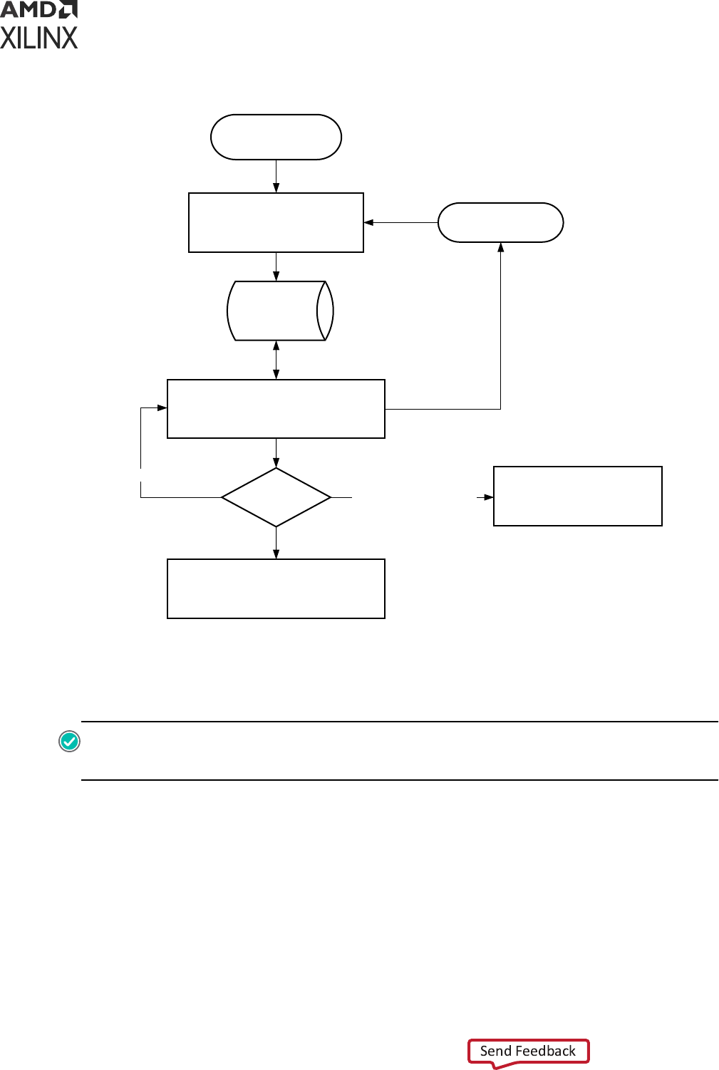
Figure 45: Creating Constraints with the Synthesized Design
Synthesized Netlist
Vivado
Database
Use Vivado IDE editors or the Tcl
Console to enter new constraints
Timing clean?
Fix RTL Design
Add Synthesis Attributes
Use different Synthesis
Options
Open (or reload)
Synthesized Design
Implementation
XDC files
YES
NO (missing constraints)
X12981
Save your constraints
Run implementation
NO (clean constraints)
Before proceeding to implementaon, you must verify that your design does not include any
major ming violaon. The place-and-route tools can x most reasonable ming violaons, but
they cannot x fundamental design issues that make ming closure impossible.
RECOMMENDED:
Revisit the RTL to reduce the number of logic levels on the violang paths and to clean
up the clock trees in order to use dedicated clock resources and minimize the skew between related clocks.
You can also add synthesis aributes and use dierent synthesis opons.
For more informaon, see this link in the Vivado Design Suite User Guide: Synthesis (UG901), or
this link in the Vivado Design Suite User Guide: Implementaon (UG904).
Chapter 2: Constraints Methodology
UG903 (v2022.1) June 1, 2022 www.xilinx.com
Using Constraints 66

Adjust Constraints for Synthesis with Black-Boxes
When using Out-Of-Context (OOC) synthesis mode, the OOC modules (IP/BD/DFx/…) are
inferred as a black-box inside the top level. This means that the netlist objects inside the OOC
modules are not accessible by the top-level constraints. This may require the top-level
constraints for synthesis to be dierent from the constraints for implementaon. In Project
Mode, this can be done by creang a specic XDC le for synthesis and seng the properes
USED_IN_SYNTHESIS=TRUE & USED_IN_IMPLEMENTATION=FALSE on it. The top-level XDC
for implementaon should have USED_IN_SYNTHESIS=FALSE.
The only objects accessible from the black-boxes are the input and output ports. This limits the
type of ming constraints that the top-level can specify when referring to a black-box.
Some of the limitaons for the top-level constraints from OOC synthesis are:
• Auto-derived clocks generated inside the OOC module cannot be renamed.
• Clock names dened inside the OOC module cannot be referred to. The clock propagang to
the output of the OOC module is named based on the net connected to the port of the
module, not from the name it has inside the module, even if the clock is renamed inside the
module XDC.
• If the top-level constraints need to refer to the clock coming out of an OOC module, it should
use a query such as ‘get_clocks -of_objects [get_pins
<MODULE_OOC_OUTPUT_CLOCK_PORT>]’.
Constraints Scoping
The constraints from a parcular XDC le can be oponally scoped to a specic module, to
specic cells of your design, or both, if needed. This is convenient for creang and applying
constraints to a sub-level of your design without having any informaon about the top-level. The
block-level constraints must be developed independently from the top-level constraints, and
must be as generic as possible so that they can be used in various contexts. They must also not
aect any logic that is beyond the block boundaries. By default, all the IP cores from the Vivado
IP catalog generated within a Vivado Design Suite project use this mechanism to load their
constraints in memory.
XDC File Scoping Properties
The constraints scoping mechanism is acvated by specifying the following properes on the
XDC les:
• SCOPED_TO_REF: This property takes the name of a module (or enty). The constraints are
applied to ALL instances of the specied module (or enty) only.
Chapter 2: Constraints Methodology
UG903 (v2022.1) June 1, 2022 www.xilinx.com
Using Constraints 67
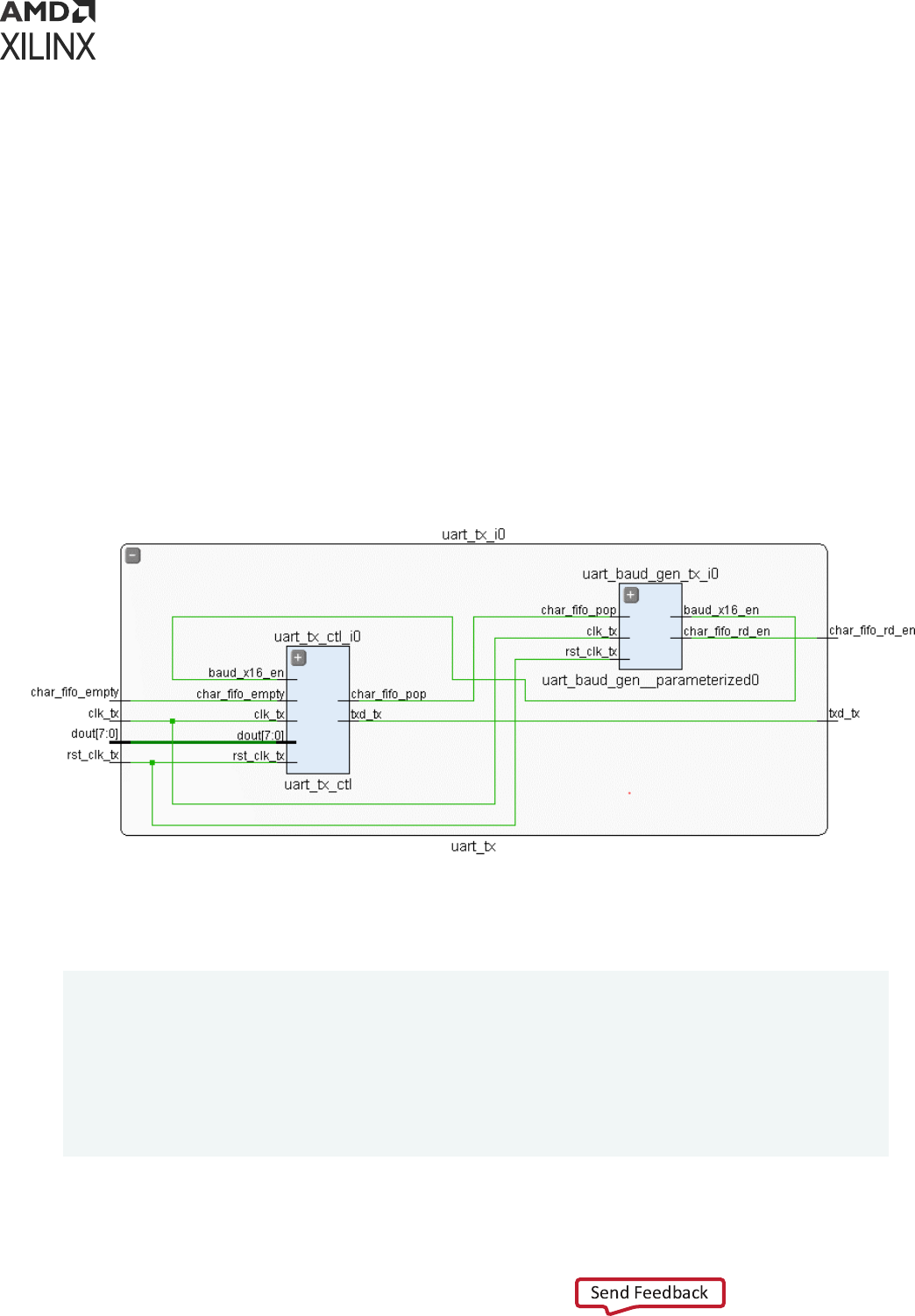
• SCOPED_TO_CELLS: This property takes a list of hierarchical cell names. The constraints are
scoped and applied to each hierarchical cell individually.
• SCOPED_TO_REF + SCOPED_TO_CELLS: If both these properes are specied, the
constraints are applied to each cell of the SCOPED_TO_CELLS list, located inside the module
(or enty) specied by SCOPED_TO_REF.
These properes are automacally set by the Vivado Design Suite for IP cores added to your RTL
project by means of the IP catalog.
Setting XDC File Scoping Properties Example
The following gure shows the uart_tx_i0 cell, an instance of the uart_tx module, which includes
two hierarchical cells, uart_tx_ctl_i0 and uart_baud_gen_tx_i0.
The project includes an XDC le uart_tx_ctl.xdc to constrain the uart_tx_ctl module.
Figure 46: Setting XDC File Scoping Properties Example
Following are three equivalent Tcl examples to use the scoping properes on
uart_tx_ctl.xdc. The same values can be set in the Properes windows of the XDC le in
the Vivado IDE.
# Using the reference module name only:
set_property SCOPED_TO_REF uart_tx_ctl [get_files uart_tx_ctl.xdc]
# Using the cell name only:
set_property SCOPED_TO_CELLS uart_tx_i0/uart_tx_ctl_i0 [get_files
uart_tx_ctl.xdc]
# Using both the uart_tx reference module and uart_tx_ctl_i0 instance:
set_property SCOPED_TO_REF uart_tx [get_files uart_tx_ctl.xdc] set_property
SCOPED_TO_CELLS uart_tx_ctl_i0 [get_files uart_tx_ctl.xdc]
Chapter 2: Constraints Methodology
UG903 (v2022.1) June 1, 2022 www.xilinx.com
Using Constraints 68

When using Vivado Design Suite in Non-Project Mode, you can use the read_xdc command
with the -ref and -cells opons to achieve the same result:
# Using the reference module name only:
read_xdc -ref uart_tx_ctl uart_tx_ctl.xdc # Using the cell name only:
read_xdc -cells uart_tx_i0/uart_tx_ctl_i0 uart_tx_ctl.xdc
# Using both the uart_tx reference module and uart_tx_ctl_i0 instance
read_xdc -ref uart_tx -cells uart_tx_ctl_i0 uart_tx_ctl.xdc
When a module is instanated mulple mes in the design, the module is uniquied during
synthesis. Aer the synthesis, each instance of the RTL module points to a dierent module
name. To apply some XDC constraints to all the instances of the original RTL module, the
property ORIG_REF_NAME should be used instead of the property REF_NAME. For example:
set_property SCOPED_TO_REF [get_cells -hierarchical -filter {ORIG_REF_NAME
== uart_tx_ctl}] [get_files uart_tx_ctl.xdc]
read_xdc -ref [get_cells -hierarchical -filter {ORIG_REF_NAME ==
uart_tx_ctl}] uart_tx_ctl.xdc
Note: When a module is uniquied, the property ORIG_REF_NAME is set on the original cell and on all the
instances that come from the uniquicaon of the original cell.
XDC Scoping Mechanism
Except for ports, constraints scoping relies on the current_instance mechanism, which is
part of the Synopsys Design Constraints (SDC) standard. When seng the scope to a lower level
of the design hierarchy with the current_instance command, only the objects included in
that level or below can be returned by the object query commands.
The only excepons are with ming clock objects and netlist ports:
• Timing clocks are dened by create_clock or create_generated_clock. They are
visible throughout the design regardless of the current instance seng. The get_clocks
command can query clocks that are not present in the current instance, or that propagate
beyond the current instance. Xilinx does not recommend dening ming excepons on clocks
when creang scoped constraints unless they are fully contained in the current instance. For a
clock to be available for reference in an XDC, the clock must have already been dened. This
might require changing the order of the XDC les in the project.
• Top-level ports are returned by the get_ports command when the scope is set to a lower
level instance with the current_instance command. But when reading an XDC le scoped
to a lower-level instance with the read_xdc -ref/-cells command or when loading a
design aer seng the SCOPED_TO_REF/SCOPED_TO_CELLS le properes, the
get_ports command behavior is dierent:
○ The port names to be used with get_ports are the port names of the scoped instance
interface, not the top-level port names.
Chapter 2: Constraints Methodology
UG903 (v2022.1) June 1, 2022 www.xilinx.com
Using Constraints 69
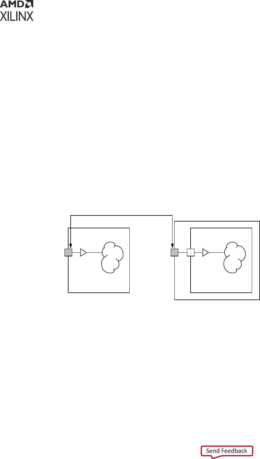
○ If a scoped instance port is directly connected to a top-level port through the hierarchy of
the design, the top-level port is returned by the get_ports command and the constraint
is applied to the top-level port.
○ If there is any leaf cell, including IO and clock buers, between the scoped instance port
and the top-level ports, the get_ports command becomes a get_pins command and
returns the hierarchical scoped instance pin.
The XDC scoping mechanism is used for reading all Vivado Design Suite IP constraint les. Figure
47, and Figure 48, show the two examples of how the get_ports commands are treated when
reading in the IP-level XDC using this methodology.
In Figure 47, the I/O buer is instanated inside the IP and the IP interface pin is directly
connected to a top-level port (regardless of the hierarchy). When the XDC for the IP is applied,
the argument of the get_ports replaced with the top-level port.
This enables seng physical properes such as a LOC or IOSTANDARD at the IP level and
having them be placed on the top-level port where they need to be. This is accomplished without
the IP knowing the name of the top-level ports of the design. command is automacally replaced
with the top-level port.
Figure 47: IP Port Migration to the Corresponding Top-Level Port
X12586
IP
top
IBUF
IP
IBUF
The following gure, the IP does not contain an I/O buer, so the synthesis engine infers one
between the IP interface pin and the top-level port. Consequently, the get_ports is converted to
a get_pins of the IP interface pin (for example, a hierarchical pin) when the XDC is applied.
Chapter 2: Constraints Methodology
UG903 (v2022.1) June 1, 2022 www.xilinx.com
Using Constraints 70
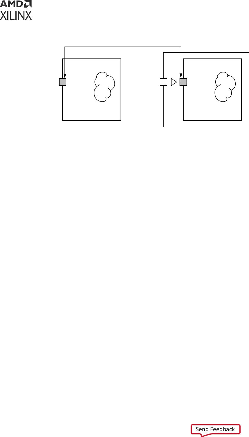
Figure 48: IP Port Migration to a Hierarchical Pin
X12587
IP
top
IP
IBUF
This capability is very useful for creang constraints on the interface of an IP or a sub-level
module without knowing the names of the top-level design.
If the scoped XDC le includes constraints that can only be applied to top-level ports but the IP
instance is not directly connected to top-level ports, the Vivado Design Suite XDC reader will
return errors. For example, the following constraints can only be applied to top-level ports, and
not hierarchical pins of your design:
• set_input_delay/set_output_delay
• set_property IOSTANDARD
IP and Sub-Module Constraining with XDC
When using Package IP to create IP and use it from the Vivado IP catalog, XDC constraints can
also be packaged for inclusion. Any IP in the Vivado Design Suite is plug-and-play, that is, the IP
does not require a sample project from which you must cut and paste constraints to complete
your top-level design constraints. Instead, the IP can be packaged with an XDC le that was
developed for the IP as if it were a stand alone, top-level design. The Vivado tools take care of
reading the constraints appropriately when the IP is instanated in the project using the IP
catalog.
Similarly, you can develop constraints for a sub-module of your design, and use the same scoping
mechanism as IP cores by seng the SCOPED_TO_REF/SCOPED_TO_CELLS XDC le properes
appropriately in a project ow, or use the read_xdc -ref/-cells command in Non-Project
Mode.
Chapter 2: Constraints Methodology
UG903 (v2022.1) June 1, 2022 www.xilinx.com
Using Constraints 71

Scoped Queries Guidelines
For this ow to work smoothly, the XDC constraints must be wrien so that the eects of the
constraints stay local to the IP or sub-module instance. The Vivado tools can set the scope of
queries to a specic level of the hierarchy as seen previously in Constraints Scoping. When
developing constraints for an IP or a sub-level module, you must understand the behavior of the
query commands:
• Cell/net/pin objects queries are limited to the scoped instance and its sub-levels:
○ get_cells/get_nets/get_pins <name pattern>
○ The NAME property of the object shows the full hierarchical path of the object relave to
the top-level and not just the scoped instance. If you use the -filter opon of the
get_* commands on the NAME property, you must use the glob string match operator
and provide a paern which starts with a *. For example:
get_nets -hierarchical -filter {NAME =~ *clk}
• get_ports returns a top-level port if the port of the block/IP is directly connected to a top-
level port. Otherwise, get_ports returns a hierarchical pin.
• Netlist helper commands are also scoped:
○ all_ffs, all_latches, all_rams, all_registers, all_dsps, all_hsios return
only instances included in the current instance.
• IO helper commands cannot be used at all in a scoped XDC:
○ all_inputs, all_outputs
• Clock commands are not scoped and will return all ming clocks of your design.
○ get_clocks, all_clocks
• Top-level and local clock objects can be queried by probing the netlist with get_clocks -
of_objects.
○ Retrieve a clock entering the current instance by using get_clocks -of_objects
[get_ports <interfacePinName>].
○ Retrieve a clock automacally generated inside the current instance by using get_clocks
-of_objects [get_pins <instName/outPin>], where instName is a clock
generator instance.
• Querying any object in the design is possible using the -of_objects opon:
○ Example: get_pins -leaf -of_objects [get_nets local_net]
• Queries are supported for top-level ports connected to the current instance interface nets:
get_ports -of_objects [get_nets <scoped_instance_net>]
Chapter 2: Constraints Methodology
UG903 (v2022.1) June 1, 2022 www.xilinx.com
Using Constraints 72

• Queries of IP/sub-module interface pins are not allowed:
○ “get_pins clk” returns an error.
• Path tracing commands are also scoped:
○ all_fanin/all_fanout traverses the scoped design and stops at its boundary.
• Use get_cells/get_pins/get_nets with the most specic paern instead of using the
all_registers command with the -clock opon to query all the cells connected to a
parcular clock. The returned list can be very large while only a few objects need to be
constrained. This can impact the runme negavely.
Scoped Timing Constraints Guidelines
To avoid negavely impacng the top-level design, it is important to make sure that ming
constraints wrien for the IP or sub-module do not propagate beyond its boundary, except for
clock denion in some cases.
For example, consider the case in which a false path constraint is dened in the IP XDC between
two clocks that come into the IP. The IP includes proper circuitry for asynchronous clock
boundaries, but perhaps not for the rest of the design. This is a problem if the two clocks are
related and must be med together in the rest of the design in order to have proper hardware
funconality.
Also, as discussed in Chapter 7: XDC Precedence, a ming excepon dened in the IP XDC le
can have higher precedence than top-level constraints and can override them, which is
undesired. To avoid this situaon, Xilinx recommends that you apply the constraints to netlist
objects local to the IP. In the case of a false path between two global clocks, the false path must
be applied from a group of startpoint cells inside the IP to another group of endpoint cells inside
the IP as well. This technique is referred to as point-to-point excepons instead of global
excepons.
Recommended Constraints Rules of IP/Sub-Module
XDC
The block-level constraints must comply with the following rules:
1. Do not dene clocks in the block-level constraints if they are expected to be created at the
top level of the design.
Instead they can be queried inside the block using the get_clocks -of_objects command. This
command returns all the clocks that traverse a parcular object in the design.
Example:
set blockClock [get_clocks -of_objects [get_ports clkIn]]
Chapter 2: Constraints Methodology
UG903 (v2022.1) June 1, 2022 www.xilinx.com
Using Constraints 73

If a clock needs to be dened inside the block, it must be on an input/inout port that is
driving an instanated input/inout buer, or on the output of a cell that creates/transforms a
clock (except for MMCM/PLL or special buers that are automacally handled by the ming
tools).
Examples:
• Input clock with input buer
• Clock Divider
• GT recovered clock
2. Specify input and output delay only if the port is directly connected to the top-level port and
the I/O buer is instanated inside the IP.
Example:
• Input data ports with input buers
• Output data ports with output buers
3. Do not dene ming excepons between two clocks that are not bounded to the IP.
4. Do not refer to clocks by name as the name may vary based on the top-level clock names or
if the block is instanated mulple mes.
5. Do not add placement constraints if the block can be instanated mulple mes in a same
top-level design.
Constraints Efficiency
Reviewing Constraints Coverage
When wring ming constraints, it is important to keep the constraints simple and specify them
on the relevant netlist objects only. Inecient constraints result in larger runme and larger
memory consumpon. Inecient constraints can also result in a design improperly constrained as
ming excepons can unexpectedly cover more paths than expected and collide with other
constraints.
A ming constraint is ecient when the number of objects provided to the constraint is as small
as possible to accurately and safely cover the desired ming paths. Most of the me, the full
eciency cannot be obtained as the list of objects are typically built from some pins or cells
name paerns. However, the minimum number of objects should always be the target when
building the list of objects for a ming excepon.
Vivado provides several ways to get feedback on the ming excepons:
Chapter 2: Constraints Methodology
UG903 (v2022.1) June 1, 2022 www.xilinx.com
Using Constraints 74

• The methodology check XDCB-1 (report_methodology) reports the ming constraints that
reference large collecons of objects (over 1000).
• The Report Excepon command (report_excepons) provides coverage and collision
informaon on the ming excepons that have been dened.
Xilinx recommends that you carefully analyze the following reports:
• report_exceptions -scope_override
This report provides the list of scoped ming constraints that a top-level ming constraint
parally or totally overrides. However, it does not report a scoped constraint overriden by
another scoped constraints (from the same scope or from a dierent scope). For example, this
opon can be used to verify that the IP constraints are not overriden by some user's top-level
constraints.
• report_exceptions –coverage
This report provides a logical path coverage for each ming excepon. The number of objects
passed to the ming excepon are compared to the number of startpoints and endpoints
eecvely covered. You should review constraints that have signicant dierences between
the number of objects and the number of startpoints/endpoints.
• report_exceptions –ignored
This report provides the list of ming constraints overridden by other ming constraints (for
example, a set_false_path overridden by set_clock_group). You should review the
overridden constraints for correctness or remove the useless constraints.
• report_exceptions –ignored_objects
This report provides the list of startpoints and endpoints that are ignored due to, for example,
inexistent paths from those startpoints or to those endpoints.
Improving Constraints Runtime
Optimizing Pin Queries
Since there are several mes mores pins than cells in the design, using get_pins instead of
get_cells can have a signicant impact on the runme. The runme degradaon can be
experienced when processing XDC constraints (for example, open_checkpoint runme) or when
execung a Tcl script. Xilinx recommends leveraging the relaonship between pin and cell objects
to improve the runme for large number of pin queries.
Instead of nding a list of pins based on their names among all pins in the design, it is more
ecient to rst nd the cells of the desired pins, and then rene the query by ltering the
desired pins of the cells returned by the rst query, as described below.
Chapter 2: Constraints Methodology
UG903 (v2022.1) June 1, 2022 www.xilinx.com
Using Constraints 75

Recommended Pin Queries
• Original pin query:
get_pins –hier * -filter {NAME=~xx*/yy*}
• Recommended ecient pin query:
get_pins –filter {REF_PIN_NAME=~yy*} –of [get_cells –hier xx*]
• Alternate recommended pin query:
get_pins –filter {REF_PIN_NAME=~yy*} –of [get_cells –hier * -filter
{NAME=~xx*}]
Example
For example, consider the following constraint:
set_max_delay 15 -from [get_pins -hier -filter {NAME=~*/aclk_dpram_reg*/*/
CLK}] \
-to [get_cells -hier -filter {NAME=~*/bclk_dout_reg*}] \
-datapath_only
The constraint above can be re-wrien as follows to signicantly improve the query runme,
especially for larger designs:
set_max_delay 15 -from [get_pins -of [get_cells -hier –filter
{NAME =~ *aclk_dpram_reg*/*}] -filter {REF_PIN_NAME == CLK}] \
-to [get_cells -hier bclk_dout_reg*] \
-datapath_only
Replacing all_registers Queries
The following are some addional query recommendaons:
• Avoid queries using all_registers whenever possible, as they tend to create large collecons of
objects. Such queries should be replaced by cells/pins queries with appropriate name paerns.
• When all_registers must be used and the query is gathering all the sequenal elements from a
clock domain, all_registers -clock can somemes have equivalent coverage as directly using a
clock object.
For example, the two commands below are equivalent in terms of coverage. However, the
second form using get_clocks is far more ecient because the mulcycle path constraint
references a single clock object instead of potenally hundreds of thousands of sequenal
elements.
Original:
set_multicycle_path –from [all_inputs] –to [all_registers –clock clk1]
Chapter 2: Constraints Methodology
UG903 (v2022.1) June 1, 2022 www.xilinx.com
Using Constraints 76
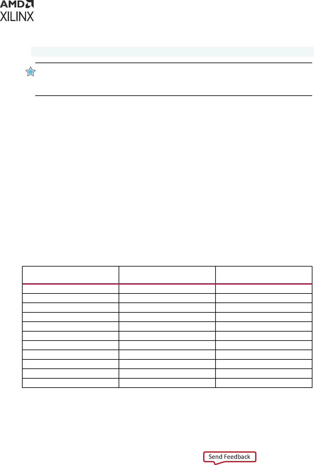
Opmal:
set_multicycle_path –from [all_inputs] –to [get_clocks clk1]
IMPORTANT! Starng with the Vivado Design Suite 2018.3, the all_registers command only returns
primives that have at least one Setup/Hold/Recovery/Removal ming arc that is enabled and a CLK->Q
ming arc. This means that buers such as BUFGCE and BUFGCE_DIV are not returned anymore by the
all_registers command.
Ordering Constraints for Better Runtime
When loading the ming constraints in memory, the ming engine validates each new constraint
and prints messages to ag potenal problems. Some ming constraints parally invalidate the
ming database (also referred as ming graph) and some other ming constraints require an up-
to-date ming database in order to be properly applied. Once the ming database is out of date,
subsequent ming updates are needed, for instance, to update auto-derivaon clocks or to
disable certain ming paths in the design. The XDC commands which query the clocks or which
traverse the design to query netlist objects require an up-to-date ming database.
Interleaving constraints and commands that impact the ming database state can be runme
intensive as the ming informaon gets invalidated and updated mulple mes.
For runme opmizaon, Xilinx
®
recommends that you order the ming constraints and queries
carefully. The table below lists the XDC constraints and commands that have an impact on the
ming graph.
Table 5: XDC Constraints and Their Impact on the Timing Graph
Constraints with Impact on
Timing Graph
Constraints with No Impact on
Timing Graph
Constraints which Require Up-
to-Date Timing Graph
create_clock set_bus_skew all_fanout
create_generated_clock set_clock_groups all_fanin
set_case_analysis set_clock_latency get_clocks
set_clock_sense set_false_path get_generated_clocks
set_clock_uncertainty set_input_delay all_clocks
set_disable_timing set_input_jitter Any constraint with the –clock option
set_external_delay set_min_delay
set_propagated_clock set_max_delay
set_max_time_borrow
set_multicycle_path
set_system_jitter
Chapter 2: Constraints Methodology
UG903 (v2022.1) June 1, 2022 www.xilinx.com
Using Constraints 77

One of the most runme intensive combinaons is set_disable_timing with all_fanout
or all_fanin. Such combinaons should be avoided. For example:
set_disable_timing –from <pin> -to [all_fanout …] set_disable_timing –from
[all_fanin …] -to <pin>
Based on the table above, the opmal constraints order for runme opmizaon is:
1. XDC constraints set_disable_timing, set_case_analysis, and
set_external_delay.
2. Constraints that have an impact on the ming graph.
3. Constraints that do not require ming graph updates.
TIP: When the same query is done in mulple places, it is recommended that you save the result of the
query inside a Tcl variable and refer to that Tcl variable when it is needed.
For example, the following sequence of constraints is not opmal.
create_clock –name clk1
create_generated_clock –name genclk1 –master_clock [get_clocks -of
[get_pins ...]] set_disable_timing ...
create_clock –name clk2
set_false_path -from [get_clocks -of [get_pins ff1/C]] set_case_analysis ...
create_clock –name clk3
set_max_delay -to [get_clocks -of [get_pins ff2/C]]
The following shows a more opmal and runme ecient sequence.
set_disable_timing ...
set_case_analysis ...
create_clock –name clk1 create_clock –name clk2
create_clock –name clk3
create_generated_clock –name genclk1 –master_clock [get_clocks -of
[get_pins ...]]
set_false_path -from [get_clocks -of [get_pins ff1/C]]
set_max_delay -to [get_clocks -of [get_pins ff2/C]]
Chapter 2: Constraints Methodology
UG903 (v2022.1) June 1, 2022 www.xilinx.com
Using Constraints 78

Chapter 3
Defining Clocks
About Clocks
In digital designs, clocks represent the me reference for reliably transferring data from register
to register. The Xilinx
®
Vivado
®
Integrated Design Environment (IDE) ming engine uses the
clock characteriscs to compute ming path requirements and report the design ming margin
by means of the slack computaon.
For more informaon, see this link in the Vivado Design Suite User Guide: Design Analysis and
Closure Techniques (UG906).
Clocks must be properly dened in order to get the maximum ming path coverage with the best
accuracy. The following characteriscs dene a clock:
• It is dened on the driver pin or port of its tree root, which is called the source point.
• Its edges are described by the combinaon of the period and the waveform properes.
• The period is specied in nanoseconds. It corresponds to the me over which the waveform
repeats.
• The waveform is the list of rising edge and falling edge absolute mes, in nanoseconds, within
the clock period. The list must contain an even number of values. The rst value always
corresponds to the rst rising edge. Unless specied otherwise, the duty cycle defaults to 50%
and the phase shi to 0 ns.
As shown in the following gure, the clock Clk0 has a 10 ns period, a 50% duty cycle and 0 ns
phase. The clock Clk1 has 8 ns period, 75% duty cycle (high me is 6 ns out of 8 ns) and a 2 ns
rising edge phase shi.
Clk0: period = 10, waveform = {0 5}
Clk1: period = 8, waveform = {2 8}
Chapter 3: Defining Clocks
UG903 (v2022.1) June 1, 2022 www.xilinx.com
Using Constraints 79
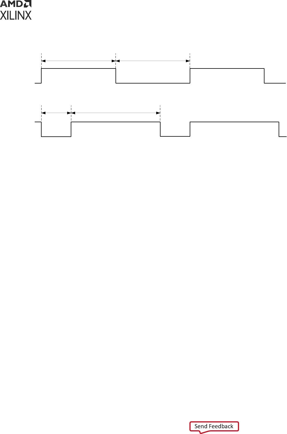
Figure 49: Clock Waveforms Example
0ns 2ns 8ns 16ns
5ns
10ns
Clk0
Clk1
0ns 10ns 15ns
50% 50%
75%25%
X14371-120415
Propagated Clocks
The period and waveform properes represent the ideal characteriscs of a clock. When entering
the FPGA and propagang through the clock tree, the clock edges are delayed and become
subject to variaons induced by noise and hardware behavior. These characteriscs are called
clock network latency and clock uncertainty.
The clock uncertainty includes:
• Clock jier (see Clock Jier)
• Phase error
• Any addional uncertainty that you have specied (see Addional Clock Uncertainty)
By default, the Vivado IDE always treats clocks as propagated clocks, that is, non-ideal, in order
to provide an accurate slack value which includes clock tree inseron delay and uncertainty.
Dedicated Hardware Resources
The dedicated hardware resources of Xilinx FPGAs eciently support a large number of design
clocks. These clocks are usually generated by an external component on the board. They usually
enter the device through an input port.
They can also be generated by special primives called Clock Modifying Blocks, such as:
• MMCM
• PLL
• BUFR
Chapter 3: Defining Clocks
UG903 (v2022.1) June 1, 2022 www.xilinx.com
Using Constraints 80

They can also be transformed by regular cells such as LUTs and registers.
The following secons describe how to best dene clocks based on where they originate.
Primary Clocks
A primary clock is a board clock that enters the design through an input port or a gigabit
transceiver output pin (for example, a recovered clock).
A primary clock can be dened only by the create_clock command.
Note: Primary clocks must be dened on a gigabit transceiver output only for Xilinx 7 series FPGAs. For
UltraScale™ and UltraScale+™ devices, the mer automacally derives clocks on the GT output ports.
A primary clock must be aached to a netlist object. This netlist object represents the point in
the design from which all the clock edges originate and propagate downstream on the clock tree.
In other words, the source point of a primary clock denes the me zero used by the Vivado IDE
when compung the clock latency and uncertainty used in the slack equaon.
IMPORTANT! The Vivado IDE ignores all clock tree delays coming from cells located upstream from the
point at which the primary clock is dened. If you dene a primary clock on a pin in the middle of the
design, only part of its latency is used for ming analysis. This can be a problem if this clock communicates
with other related clocks in the design, because the skew, and consequently the slack, value between the
clocks can be inaccurate.
Primary clocks must be
dened rst, because other ming constraints oen refer to them.
Primary Clocks Examples
As shown in the following gure, the board clock enters the device through the port sysclk,
then propagates through an input buer and a clock buer before reaching the path registers.
• Its period is 10 ns.
• Its duty cycle is 50%.
• Its phase is not shied.
Chapter 3: Defining Clocks
UG903 (v2022.1) June 1, 2022 www.xilinx.com
Using Constraints 81
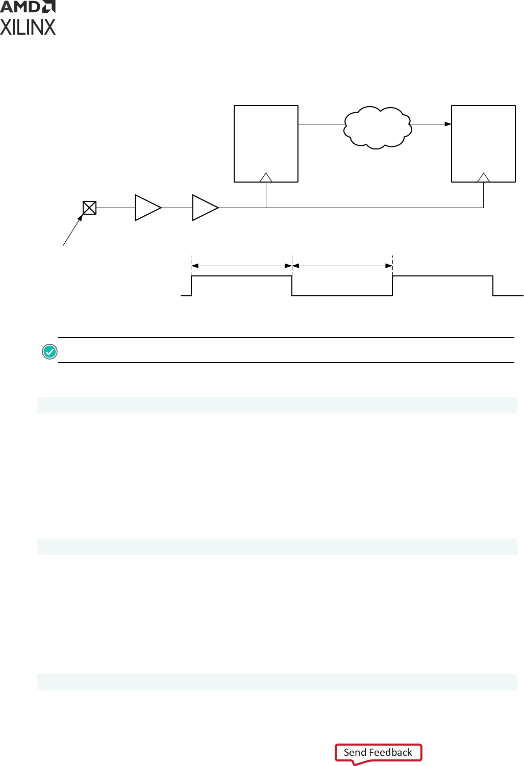
Figure 50: Primary Clock Example
5ns
sysclk
0ns 10ns 15ns
50% 50%
REGB
D Q
REGA
D Q
Data Path
sysclk
IBUF BUFG
Recommended
primary clock
source point
X14378-120415
RECOMMENDED: Dene the board clock on the input port, not on the output of the clock buer.
Corresponding Xilinx Design Constraints (XDC):
create_clock -period 10 [get_ports sysclk]
Similar to sysclk, a board clock devclk enters the device through the port ClkIn.
• Its period is 10 ns.
• Its duty cycle is 25%.
• It is phase shied by 90 degrees.
Corresponding XDC:
create_clock -name devclk -period 10 -waveform {2.5 5} [get_ports ClkIn]
The following gure shows a transceiver gt0, which recovers the clock rxclk from a high speed
link on the board. The clock rxclk has a 3.33 ns period, a 50% duty cycle and is routed to an
MMCM, which generates several compensated clocks for the design.
When dening rxclk on the output driver pin of GT0, all the generated clocks driven by the
MMCM have a common source point, which is gt0/RXOUTCLK. The slack computaon on paths
between them uses the proper clock latency and uncertainty values.
create_clock -name rxclk -period 3.33 [get_pins gt0/RXOUTCLK]
Chapter 3: Defining Clocks
UG903 (v2022.1) June 1, 2022 www.xilinx.com
Using Constraints 82
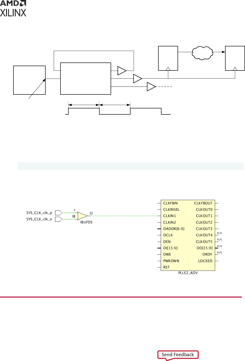
Figure 51: GT Primary Clock Example
1.66ns
rxclk
0ns 3.33ns
50% 50%
REGB
D Q
REGA
D Q
Data Path
Recommended
primary clock
source point
gt0
RXOUTCLK
CLKFBOUT
CLKOUT0
CLKOUT1
CLKIN1
CLKFBIN
mmcm0
rxclk
X14374-120415
In the following gure, a dierenal buer drives the PLL. In such a scenario, the primary clock
must only be created on the posive input of the dierenal buer. Creang a primary clock on
each of the posive/negave inputs of the buer would result in unrealisc CDC paths. For
example:
create_clock -name sysclk -period 3.33 [get_ports SYS_CLK_clk_p]
Figure 52: Primary Clock on Differential Buffer Example
X18852-052022
Virtual Clocks
A virtual clock is a clock that is not physically aached to any netlist element in the design.
Chapter 3: Defining Clocks
UG903 (v2022.1) June 1, 2022 www.xilinx.com
Using Constraints 83

A virtual clock is dened by means of the create_clock command without specifying a source
object.
A virtual clock is commonly used to specify input and output delay constraints in one of the
following situaons:
• The external device I/O reference clock is not one of the design clocks.
• The FPGA I/O paths are related to an internally generated clock that cannot be properly med
against the board clock from which it is derived.
Note: This happens when the rao between the two periods is not an integer. which leads to a very
ght and unrealisc ming path requirement.
• You want to specify dierent jier and latency only for the clock related to the I/O delay
constraints without modifying the internal clocks characteriscs.
For example, the clock clk_virt has a period of 10 ns and is not aached to any netlist object.
The [<objects>] argument is not specied. The -name opon is mandatory in such cases.
create_clock -name clk_virt -period 10
The virtual clocks must be dened before being used by the input and output delay constraints.
Generated Clocks
This secon discusses generated clocks and includes:
• About Generated Clocks
• User Dened Generated Clocks
• Automacally Derived Clocks
• Automacally Derived Clocks
About Generated Clocks
Generated clocks are driven inside the design by special cells called Clock Modifying Blocks (for
example, an MMCM), or by some user logic.
Generated clocks are associated with a master clock. The create_generated_clock
command considers the start point of the master clock. The master clock can be a primary clock
or another generated clock.
Generated clock properes are directly derived from their master clock. Instead of specifying
their period or waveform, you must describe how the modifying circuitry transforms the master
clock.
Chapter 3: Defining Clocks
UG903 (v2022.1) June 1, 2022 www.xilinx.com
Using Constraints 84

The relaonship between a master clock and a generated clock can be any of the following:
• A simple frequency division
• A simple frequency mulplicaon
• A combinaon of a frequency mulplicaon and division in order to obtain a non-integral rao
(usually done by MMCM and PLL)
• A phase shi or a waveform inversion
• A duty cycle transformaon
• A combinaon of all the above
RECOMMENDED: Dene all primary clocks rst. They are needed for dening the generated clocks.
Note: To compute the latency for the generated clock, the tool traces both sequenal and combinaonal
paths between the source pin of the generated clock and the source pin of the master clock. In some cases,
it might be desirable to only trace through combinaonal paths to calculate the generated clock latency.
You can do this using the -combinational command line opon.
User Defined Generated Clocks
A user dened generated clock is:
• Dened by the create_generated_clock command.
• Aached to a netlist object, preferably the clock tree root pin.
Specify the master clock using the -source opon. This indicates a pin or port in the design
through which the master clock propagates. It is common to use the master clock source point or
the input clock pin of generated clock source cell.
IMPORTANT!
The
-source
opon accepts only a pin or port netlist object. It does not accept clock
objects.
Example One: Simple Division by 2
The primary clock clkin has a period of 10 ns. It is divided by 2 by the register REGA which
drives other registers clock pin. The corresponding generated clock is called clkdiv2.
Two equivalent constraints are provided below:
create_clock -name clkin -period 10 [get_ports clkin]
# Option 1: master clock source is the primary clock source point
create_generated_clock -name clkdiv2 -source [get_ports clkin] -divide_by 2
\
Chapter 3: Defining Clocks
UG903 (v2022.1) June 1, 2022 www.xilinx.com
Using Constraints 85
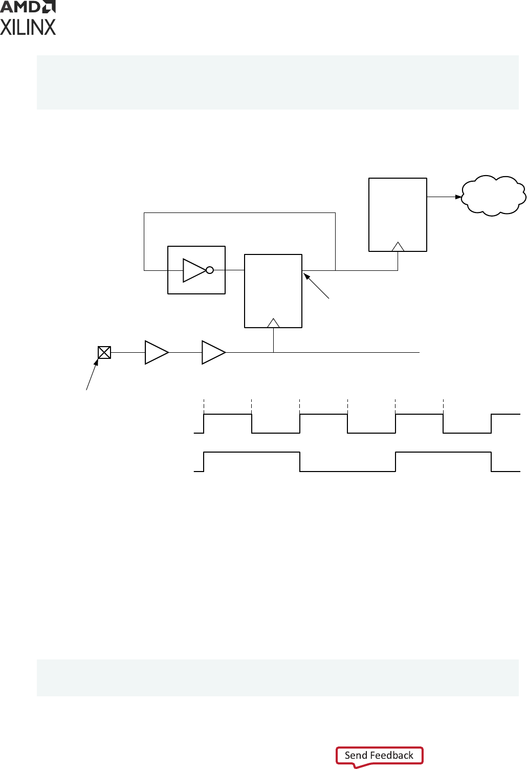
[get_pins REGA/Q]
# Option 2: master clock source is the REGA clock pin
create_generated_clock -name clkdiv2 -source [get_pins REGA/C] -divide_by 2
\ [get_pins REGA/Q]
Figure 53: Generated Clock Example One
10ns
clkin
0ns 20ns 30ns
REGB
D
Q
REGA
Data Path
clkin
IBUF BUFG
Primary clock source point
D
Q
C
Generated clock definition
point
clkdiv2
1 2 3 4 5 6
(edge#)
X14372-120415
Example Two: Division by 2 With the -edges Option
Instead of using the -divide_by opon, you can use the -edges opon to directly describe
the waveform of the generated clock based on the edges of the master clock. The argument is a
list of master clock edge indexes used for dening the posion in me of the generated clock
edges, starng with the rising clock edge.
The following example is equivalent to the generated clock dened in Example One: Simple
Division by 2.
# waveform specified with -edges instead of -divide_by
create_generated_clock -name clkdiv2 -source [get_pins REGA/C] -edges {1 3
5} \ [get_pins REGA/Q]
Chapter 3: Defining Clocks
UG903 (v2022.1) June 1, 2022 www.xilinx.com
Using Constraints 86
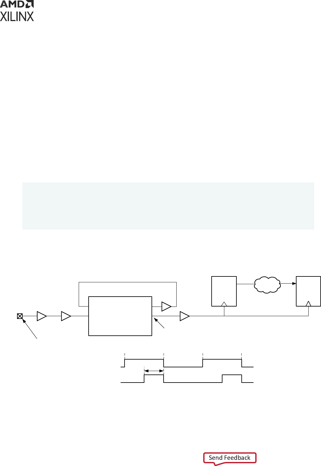
Example Three: Duty Cycle Change and Phase Shift with -edges and
-edge_shift Options
Each edge of the generated clock waveform can also be individually shied by a posive or
negave value by using the -edge_shift opon. Use this opon only if a phase shi is needed.
The -edge_shift opon cannot be used at the same me as any of the following:
• -divide_by
• -multiply_by
• -invert
Consider the master clock clkin with a 10 ns period and a 50% duty cycle. It reaches the cell
mmcm0 which generates a clock with a 25% duty cycle, shied by 90 degrees. The generated
clock denion refers to the master clock edges 1, 2, and 3. These edges respecvely occur at 0
ns, 5 ns, and 10 ns. To obtain the desired waveform, shi the rst and the third edges by 2.5 ns.
create_clock -name clkin -period 10 [get_ports clkin]
create_generated_clock -name clkshift -source [get_pins mmcm0/CLKIN] -edges
{1 2 3} \
-edge_shift {2.5 0 2.5} [get_pins mmcm0/CLKOUT] # First rising edge: 0ns
+ 2.5ns = 2.5ns
# Falling edge: 5ns + 0ns = 5ns
# Second rising edge: 10ns + 2.5ns = 12.5ns
Note: The -edge_shift values can be posive or negave.
Figure 54: Generated Clock Example Three
25%
REGB
D Q
REGA
D Q
Data Path
CLKFBOUT
CLKOUTCLKIN
CLKFBIN
mmcm0
clkin
IBUF BUFG
BUFG
BUFG
5ns
clkin
0ns 10ns 15ns
clkdiv2
1 2 3 4
(edge#)
2.5ns 12.5ns
Primary clock
source point
Generated clock
definition point
X14373-120415
Chapter 3: Defining Clocks
UG903 (v2022.1) June 1, 2022 www.xilinx.com
Using Constraints 87

Example Four: Using Both -divide_by and -multiply_by at the Same
Time
The Vivado IDE allows you to specify both -divide_by and -multiply_by at the same me.
This is an extension to standard Synopsys Design Constraints (SDC) support. This is parcularly
convenient for manually dening clocks generated by MMCM or PLL instances, although Xilinx
recommends that you let the engine create these constraints automacally.
For more informaon, see Automacally Derived Clocks.
Consider the mmcm0 cell as in Example Three: Duty Cycle Change and Phase Shi with -edges
and -edge_shi Opons above, and assume that it mulplies the frequency of the master clock
by 4/3. The corresponding generated clock denion is:
create_generated_clock -name clk43 -source [get_pins mmcm0/CLKIN] -
multiply_by 4 \
-divide_by 3 [get_pins mmcm0/CLKOUT]
If you create a generated clock constraint on the output of an MMCM or PLL, it is beer to verify
that the waveform denion matches the conguraon of the MMCM or PLL.
Example Five: Tracing the Master Clock through Combinational Arcs
Only
In this example, assume that the master clock drives both a register-based clock divided-by-2 and
a clock mulplexer that can select the master clock or the divided-by-2 clock from the register
clock divider. In this scenario, there are two paths from the master clock to the generated clock,
which are through a sequenal arc and through a combinaonal arc. You want to create a
generated clock on the mulplexer output that reects the latency of the combinaonal path
from the master clock through the mulplexer. This is done by using the -combinational
command line opon:
create_generated_clock -name clkout -source [get_pins mmcm0/CLKIN] -
combinational [get_pins MUX/O]
Example Six: Forwarded Clock Driven by ODDR
In this example, a forwarded clock is created on the output port driven by an ODDR cell. The
forwarded clock references the master clock driving the ODDR/CLKDIV pin and has the same
period as the master clock (-divide_by 1):
create_generated_clock -name ck_vsf_clk_2 \
-source [get_pins ODDRE1_vsfclk2_inst/CLKDIV] -divide_by 1 [get_ports
vsf_clk_2]
Chapter 3: Defining Clocks
UG903 (v2022.1) June 1, 2022 www.xilinx.com
Using Constraints 88
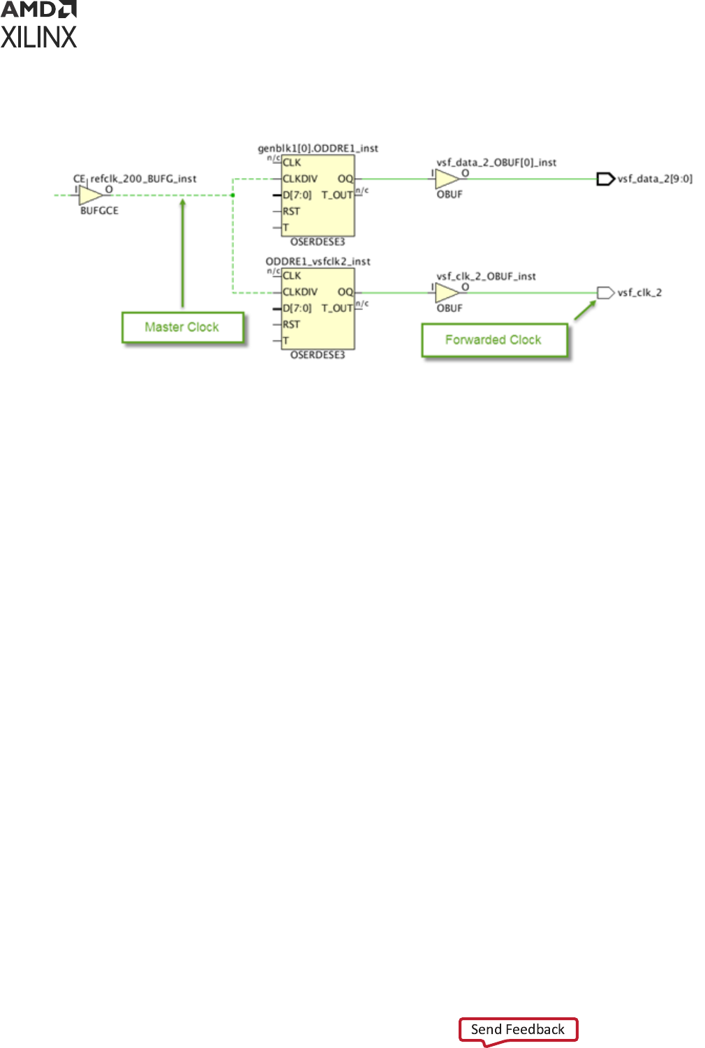
Figure 55: Example of Forwarded Clock
Automatically Derived Clocks
Automacally derived clocks are also called auto-generated clocks. The Vivado IDE automacally
creates the constraint for these on the output pins of the Clock Modifying Blocks (CMBs),
provided the associated master clock has already been dened.
In the Xilinx 7 series device family, the CMBs are:
• MMCM*/ PLL*
• BUFR
• PHASER*
In the Xilinx UltraScale™ device family, the CMBs are:
• MMCM* / PLL*
• BUFG_GT / BUFGCE_DIV
• GT*_COMMON / GT*_CHANNEL / IBUFDS_GTE3
• BITSLICE_CONTROL / RX*_BITSLICE
• ISERDESE3
An auto-generated clock is not created if a user-dened clock (primary or generated) is also
dened on the same netlist object, that is, on the same denion point (net or pin). The auto-
derived clock is named with the segment name in the top-most hierarchy of the net that is
connected to the denion point.
Chapter 3: Defining Clocks
UG903 (v2022.1) June 1, 2022 www.xilinx.com
Using Constraints 89
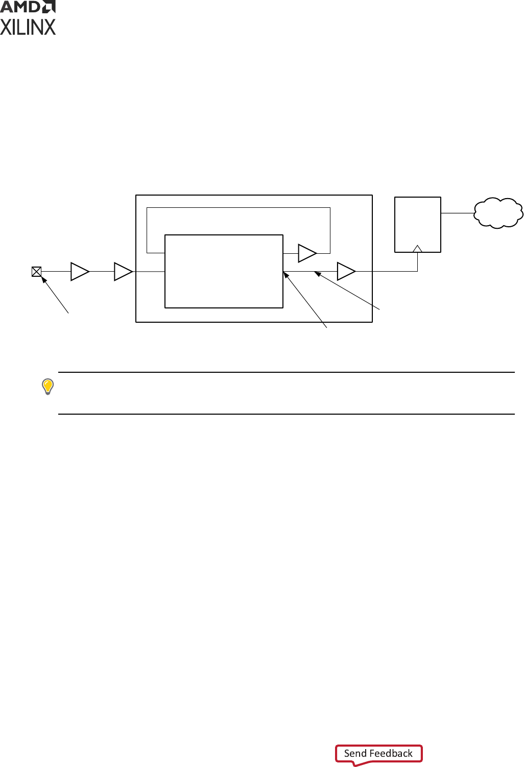
Automatically Derived Clock Example
The following automacally derived clock example is a clock generated by an MMCM.
The master clock clkin drives the input CLKIN of the MMCME2 instance clkip/mmcm0. The
name of the auto-generated clock is cpuClk and its denion point is clkip/mmcm0/CLKOUT.
Figure 56: Auto Generated Clock Example
REGA
D Q
Data Path
CLKFBOUT
CLKOUTCLKIN
CLKFBIN
clkip/mmcm0
clkin
IBUF BUFG
BUFG
BUFG
Primary clock source
point
Auto-generated clock
definition point
Hierarchical net
name: clkip/cpuClk
clkip
X14370-120415
TIP: Use the
get_clocks -of_objects <pin/port/net>
command to query an auto-generated
clock without knowing its name. This will make your constraint or script independent of the clock name
changes.
Local Net Names
If the CMB instance is located inside the hierarchy of the design, the local net name (that is, the
name without its parent cell name) is used for the generated clock name.
For example, for a hierarchical net called clkip/cpuClk:
• The parent cell name is clkip.
• The generated clock name is cpuClk.
Name Conflicts
In case of name conict between two auto-generated clocks, the Vivado IDE adds unique
suxes to dierenate them, such as:
• usrclk
• usrclk_1
• usrclk_2
Chapter 3: Defining Clocks
UG903 (v2022.1) June 1, 2022 www.xilinx.com
Using Constraints 90

• ...
To force the name of the generated clocks:
• Choose unique and relevant net names in the RTL, or
• Use create_generated_clock to force the name of the generated clocks.
Renaming Auto-Derived Clocks
It is possible to rename the generated clocks that are automacally created by the tool. The
renaming process consists in calling the create_generated_clock command with a limited
number of parameters:
create_generated_clock -name new_name [-source master_pin] [-master_clock
master_clk] source_object
The arguments that must be specied are the new generated clock name and the source object
of the generated clock. The source object of the generated clock is the object where the auto-
derived clock is created (CMB output pin, GT output pin for UltraScale, and so on). The -source
and -master parameters must be used only when more than one clock propagates through the
source pin in order to remove any ambiguity.
IMPORTANT!
If any of the
-edges
/
-edge_shift
/-
divide_by
/
-multiply_by
/
-
combinational
/
-duty_cycle
/
-invert
opons is passed to the
create_generated_clock
command, the generated clock is not renamed. Instead a new generated clock is created with the specied
characteriscs.
IMPORTANT! When a module (IP/BD/DFx/...) is synthesized Out-Of-Context, the module is inferred as a
black-box when the top level is synthesized and the module internal pins and clock names are not anymore
accessible. In that scenario, the top level XDC constraints used for synthesis cannot refer to a clock name
or rename an auto-derived clock that is generated inside the module. With OOC synthesis, the top-level
ming constraints must point to the OOC clocks through the module ports that propagate those clocks.
This can be done using some queries such as
‘get_clocks -of_objects [get_pins
<OOC_MODULE_OUTPUT_CLOCK_PORT>]
. The XDC constraints used for implementaon do not have
this limitaon since the enre design is rebuilt before the XDC constraints are applied.
Limitations
• Auto-derived clocks can only be renamed at the pin where they originate, such as at the
output of the Clock Modifying blocks (PLL, MMCM, . . .). For example, an auto-derived clock
cannot be renamed at the output of a BUFG even though it propagates through it.
• Primary clocks or user-dened generated clocks cannot be renamed. Only auto-derived clocks
can be renamed with this mechanism.
• The source_object must match the object where the auto-derived clock is created.
Chapter 3: Defining Clocks
UG903 (v2022.1) June 1, 2022 www.xilinx.com
Using Constraints 91

An error is returned if the tool cannot rename the generated clock. The master clock must also
exist at the me the renaming is done. The auto-derived clocks can be renamed at any me
inside the XDC, even aer they have been referenced by some ming constraints.
For example, below is an abstract of report_clocks for the generated clock at the output pins of
an MMCM:
====================================================
Generated Clocks
====================================================
Generated Clock : clkfbout_clk_core
Master Source : clk_gen_i0/clk_core_i0/inst/mmcm_adv_inst/CLKIN1 Master
Clock : clk_pin_p
Multiply By : 1
Generated Sources : {clk_gen_i0/clk_core_i0/inst/mmcm_adv_inst/CLKFBOUT}
Generated Clock : clk_rx_clk_core
Master Source : clk_gen_i0/clk_core_i0/inst/mmcm_adv_inst/CLKIN1 Master
Clock : clk_pin_p
Multiply By : 1
Generated Sources : {clk_gen_i0/clk_core_i0/inst/mmcm_adv_inst/CLKOUT0}
Generated Clock : clk_tx_clk_core
Master Source : clk_gen_i0/clk_core_i0/inst/mmcm_adv_inst/CLKIN1 Master
Clock : clk_pin_p
Edges : {1 2 3}
Edge Shifts : {0.000 0.500 1.000}
Generated Sources : {clk_gen_i0/clk_core_i0/inst/mmcm_adv_inst/CLKOUT1}
The three commands below illustrate the command line opons that must be specied to rename
the three auto-derived clocks at the output of the MMCM:
create_generated_clock -name clk_rx [get_pins clk_gen_i0/clk_core_i0/inst/
mmcm_adv_inst/CLKOUT0]
create_generated_clock -name clk_tx [get_pins clk_gen_i0/clk_core_i0/inst/
mmcm_adv_inst/CLKOUT1]
create_generated_clock -name clkfbout [get_pins clk_gen_i0/clk_core_i0/inst/
mmcm_adv_inst/CLKFBOUT]
Aer the renaming, below is the abstract from the report_clocks:
====================================================
Generated Clocks
====================================================
Generated Clock : clkfbout
Master Source : clk_gen_i0/clk_core_i0/inst/mmcm_adv_inst/CLKIN1 Master
Clock : clk_pin_p
Multiply By : 1
Generated Sources : {clk_gen_i0/clk_core_i0/inst/mmcm_adv_inst/CLKFBOUT}
Generated Clock : clk_rx
Master Source : clk_gen_i0/clk_core_i0/inst/mmcm_adv_inst/CLKIN1 Master
Clock : clk_pin_p
Multiply By : 1
Generated Sources : {clk_gen_i0/clk_core_i0/inst/mmcm_adv_inst/CLKOUT0}
Chapter 3: Defining Clocks
UG903 (v2022.1) June 1, 2022 www.xilinx.com
Using Constraints 92

Generated Clock : clk_tx
Master Source : clk_gen_i0/clk_core_i0/inst/mmcm_adv_inst/CLKIN1 Master
Clock : clk_pin_p
Edges : {1 2 3}
Edge Shifts : {0.000 0.500 1.000}
Generated Sources : {clk_gen_i0/clk_core_i0/inst/mmcm_adv_inst/CLKOUT1}
Clock Groups
This secon discusses Clock Groups and includes:
• About Clock Groups
• Clock Categories
• Asynchronous Clock Groups
• Exclusive Clock Groups
About Clock Groups
The Vivado IDE mes the paths between all the clocks in your design by default, unless you
specify otherwise by using clock groups or false path constraints. The set_clock_groups
command disables ming analysis between groups of clocks that you idenfy, and not between
the clocks within a same group. Unlike with the set_false_path constraint, ming is ignored
on both direcons between the clocks.
Mulple groups of clocks can be specied using the -group opon mulple mes. If none of the
clocks in a group exist in the design, the group becomes empty. The set_clock_groups
constraint stays valid only when at least two groups are valid and not empty. If only one group
remains valid and all the other groups are empty, then the set_clock_groups constraint is not
applied and an error message is generated.
Use the schemac viewer or the Clock Networks Report to visualize the topology of the clock
trees, and determine which clocks must not be med together. You can also use the Clock
Interacons Report to review the exisng constraints between two clocks, and determine
whether they share the same primary clock -- that is, they have a known phase relaonship -- or
idenfy the clocks with no common period (unexpandable).
CAUTION!
Ignoring ming analysis between two clocks does not mean that the paths between them will
work properly in hardware. In order to prevent metastability, you must verify that these paths have proper
re-synchronizaon circuitry, or asynchronous data transfer protocols.
Clock Categories
This secon discusses synchronous, asynchronous, and unexpandable clocks.
Chapter 3: Defining Clocks
UG903 (v2022.1) June 1, 2022 www.xilinx.com
Using Constraints 93

Synchronous Clocks
Two clocks are synchronous when their relave phase is predictable. This is usually the case
when their tree originates from the same root in the netlist, and when they have a common
period.
For example, a generated clock and its master clock that have a period rao of 2 are synchronous
because they propagate through the same netlist resources up to the generated clock source
point, and have a common period of 2 cycles. They can be safely med together.
Asynchronous Clocks
Two clocks are asynchronous when it is impossible to determine their relave phase.
For example, two clocks generated by separate oscillators on the board and entering the FPGA
by means of dierent input ports have no known phase relaonship. They must therefore be
treated as asynchronous. If they were generated by the same oscillator on the board, this would
not be true.
In most cases, primary clocks can be treated as asynchronous. When associated with their
respecve generated clocks, they form asynchronous clock groups.
Unexpandable Clocks
Two clocks are not expandable when the ming engine cannot determine their common period
over 1000 cycles. In this case, the worst setup relaonship over the 1000 cycles is used during
ming analysis, but the ming engine cannot ensure this is the most pessimisc case.
This is typically the case between two clocks with an odd fraconal period rao. For example,
consider two clocks, clk0 and clk1, generated by two MMCMs that share the same primary
clock:
• clk0 has a 5.125 ns period.
• clk1 has a 6.666 ns period.
Their rising clock edges do not realign within 1000 cycles. The ming engine uses a setup path
requirement of 0.01 ns on the ming paths between the two clocks. Even if the two clocks have
a known phase relaonship at their clock tree root, their waveforms do not allow safe ming
analysis between them.
As with asynchronous clocks, the slack computaon appears normally, but the value cannot be
trusted. For this reason, unexpandable clocks are oen assimilated to asynchronous clocks. Both
clock categories must be treated the same way for constraining and clock-domain crossing
circuitry.
Chapter 3: Defining Clocks
UG903 (v2022.1) June 1, 2022 www.xilinx.com
Using Constraints 94

Asynchronous Clock Groups
Asynchronous clocks and unexpandable clocks cannot be safely med. The ming paths between
them can be ignored during analysis by using the set_clock_groups command.
IMPORTANT! The
set_clock_groups
command has higher priority over the regular ming
excepons. If you need to constrain and report some paths between asynchronous clocks, you must use
the ming excepons only, and not
set_clock_groups
.
Asynchronous Clock Groups Examples
• The primary clock clk0 is dened on an input port and reaches an MMCM which generates
the clocks usrclk and itfclk.
• A second primary clock clk1 is a recovered clock dened on the output of a GTP instance
and reaches a second MMCM which generates the clocks gtclkrx and gtclktx.
Creating Asynchronous Clock Groups
Use the -asynchronous opon to create asynchronous groups.
set_clock_groups -name async_clk0_clk1 -asynchronous -group {clk0 usrclk
itfclk} \
-group {clk1 gtclkrx gtclktx}
If the name of the generated clocks cannot be predicted in advance, use get_clocks -
include_generated_clocks to dynamically retrieve them. The -
include_generated_clocks opon is an SDC extension. The previous example can also be
wrien as:
set_clock_groups -name async_clk0_clk1 -asynchronous \
-group [get_clocks -include_generated_clocks clk0] \
-group [get_clocks -include_generated_clocks clk1]
Exclusive Clock Groups
Some designs have several operaon modes that require the use of dierent clocks. The
selecon between the clocks is usually done with a clock mulplexer such as BUFGMUX and
BUFGCTRL, or A LUT.
RECOMMENDED:
Avoid using LUTs in clock trees as much as possible.
Because these cells are combinatorial cells, the Vivado IDE propagates all incoming clocks to the
output. With the Vivado IDE, several ming clocks can exist on a clock tree at the same me,
which is convenient for reporng on all the operaon modes at once, but is not possible in
hardware.
Chapter 3: Defining Clocks
UG903 (v2022.1) June 1, 2022 www.xilinx.com
Using Constraints 95

Such clocks are called exclusive clocks. Constrain them as such by using the opons of
set_clock_groups:
• -logically_exclusive
• -physically_exclusive
Exclusive Clock Groups Example
An MMCM instance generates clk0 and clk1 which are connected to the BUFGMUX instance
clkmux. The output of clkmux drives the design clock tree.
By default, the Vivado IDE analyzes paths between clk0 and clk1 even though both clocks share
the same clock tree and cannot exist at the same me.
You must enter the following constraint to disable the analysis between the two clocks:
set_clock_groups -name exclusive_clk0_clk1 -physically_exclusive \
-group clk0 -group clk1
The following opons are equivalent in the context of Xilinx FPGAs:
• -logically_exclusive
• -physically_exclusive
The physically and logically labels refer to various signal integrity analysis (crosstalk) modes in
ASIC technologies which is not needed for Xilinx FPGAs.
Clock Latency, Jitter, and Uncertainty
In addion to dening the clock waveforms, you must specify predictable and random variaons
related to the operang condions and environment.
Clock Latency
Aer propagang on the board and inside the FPGA, the clock edges arrive at their desnaon
with a certain delay. This delay is typically represented by:
• The source latency (delay before the clock source point, usually, outside the device)
• The network latency
The delay introduced by the network latency (also called inseron delay) is either automacally
esmated (pre-route design) or accurately computed (post-route design).
Chapter 3: Defining Clocks
UG903 (v2022.1) June 1, 2022 www.xilinx.com
Using Constraints 96

Many non-Xilinx ming engines require the SDC command set_propagated_clock to trigger
the computaon of propagaon delay along the clock trees. The Vivado tool does not require
this command. Instead, it computes the clock propagaon delay by default:
• All clocks are considered propagated clocks.
• A generated clock latency includes the inseron delay of its master clock plus its own network
latency.
For Xilinx FPGAs, use the set_clock_latency command primarily to specify the clock latency
outside the device.
set_clock_latency Example
# Minimum source latency value for clock sysClk (for both Slow and Fast
corners) set_clock_latency -source -early 0.2 [get_clocks sysClk]
# Maximum source latency value for clock sysClk (for both Slow and Fast
corners) set_clock_latency -source -late 0.5 [get_clocks sysClk]
Clock Uncertainty
Clock Jitter
For ASIC devices, clock jier is usually represented with the clock uncertainty characterisc.
However, for Xilinx FPGAs, the jier properes are predictable. They can be automacally
computed by the ming analysis engine, or be specied separately.
Input Jitter
Input jier is the dierence between successive clock edges with respect to variaon from the
nominal or ideal clock arrival mes. The input jier is an absolute value and represents variaons
on each side of the clock edge.
Use the set_input_jitter command to specify input jier for each primary clock
individually. You cannot specify the input jier on a generated clock directly. The Vivado IDE
ming engine automacally computes the jier that a generated clock inherits from its master
clock.
• For the case in which the generated clock is driven by a MMCM or a PLL, the input jier is
replaced with a computed discrete jier.
• For the case the generated clock is created by a combinatorial or sequenal cell, the
generated clock jier is the same as its master clock jier.
System Jitter
System jier is the overall jier due to power supply noise, board noise, or any extra jier of the
system.
Chapter 3: Defining Clocks
UG903 (v2022.1) June 1, 2022 www.xilinx.com
Using Constraints 97

Use the set_system_jitter command to set only one value for the whole design, that is, all
the clocks.
The following command sets a +/-100 ps jier on the primary clock propagang through input
port clkin:
set_input_jitter [get_clocks -of_objects [get_ports clkin]] 0.1
Note: The impact of input jier and system jier in the overall calculaon of the clock uncertainty is not
trivial and does not follow a single equaon. The calculaon of the clock uncertainty is path-dependent
and depends on the clocking topology, the clock-pair involved in the path, the presence or not of an
MMCM/PLL on the clock tree, and other consideraons. However, the text and GUI of the Report Timing
command expose the breakdown of the clock uncertainty for each ming path.
Additional Clock Uncertainty
Use the set_clock_uncertainty command to dene addional clock uncertainty for
dierent corner, delay, or parcular clock relaonships as needed. This is a convenient way to
add extra margin to a poron of the design from a ming perspecve.
The inter-clock uncertainty always takes precedence over simple clock uncertainty, regardless of
the order of the constraints. In the following example, although a simple clock uncertainty of 1.0
ns is dened last on clock clk1, the ming paths from clock clk1 to clock clk2 are constrained
with a 2.0 ns clock uncertainty.
set_clock_uncertainty 2.0 -from [get_clocks clk1] -to [get_clocks clk2]
set_clock_uncertainty 1.0 [get_clocks clk1]
When an inter-clock uncertainty is dened between two clock domains, make sure to constrain
all the possible interacons of clock domains:
• clk1 to clk2
• clk2 to clk1
Chapter 3: Defining Clocks
UG903 (v2022.1) June 1, 2022 www.xilinx.com
Using Constraints 98

Chapter 4
Constraining I/O Delay
About Constraining I/O Delay
To accurately model the external ming context in your design, you must give ming informaon
for the input and output ports. Because the Xilinx
®
Vivado
®
Integrated Design Environment (IDE)
recognizes ming only within the boundaries of the FPGA, you must use the following
commands to specify delay values that exist beyond these boundaries:
• set_input_delay
• set_output_delay
Input Delay
The set_input_delay command species the input path delay on an input port relave to a
clock edge at the interface of the design.
VIDEO:
For training on input delay, see the Vivado Design Suite QuickTake Video: Seng Input Delay.
When considering the applicaon board, the input delay represents the phase dierence
between:
1. The data propagang from an external chip through the board to an input package pin of the
FPGA, and
2. The relave reference board clock.
Consequently, the input delay value can be posive or negave, depending on the clock and data
relave phase at the interface of the device.
Note: Input delays can also be set on internal data pins such as, STARTUPE3/DATA_IN[0:3] (UltraScale+™
devices).
Chapter 4: Constraining I/O Delay
UG903 (v2022.1) June 1, 2022 www.xilinx.com
Using Constraints 99

Using Input Delay Options
Although the -clock opon is oponal in the Synopsys Design Constraints (SDC) standard, it is
required by the Vivado IDE. The relave clock can be either a design clock or a virtual clock.
RECOMMENDED: When using a virtual clock, use the same waveform as the design clock related to the
input ports inside the design. This way, the ming path requirement is realisc. Using a virtual clock is
convenient for modeling dierent jier or source latency scenarios without modifying the design clock.
The Input Delay command opons are:
• Min and Max Input Delay Command Opons
• Clock Fall Input Delay Command Opon
• Add Delay Input Delay Command Opon
Min and Max Input Delay Command Options
The -min and -max opons specify dierent values for:
• Min delay analysis (hold/removal)
• Max delay analysis (setup/recovery)
If neither is used, the input delay value applies to both min and max.
Clock Fall Input Delay Command Option
The -clock_fall opon species that the input delay constraint applies to ming paths
launched by the falling clock edge of the relave clock. Without this opon, the Vivado IDE
assumes only the rising edge of the relave clock.
Do not confuse the -clock_fall opon with the -rise and -fall opons. These opons
refer to the data edge and not to the clock edge.
Add Delay Input Delay Command Option
The -add_delay opon must be used if:
• A max (or min) input delay constraint exists, and
• You want to specify a second max (or min) input delay constraint on the same port.
This opon is commonly used to constrain an input port relave to more than one clock edge, as,
for example, DDR interfaces.
Chapter 4: Constraining I/O Delay
UG903 (v2022.1) June 1, 2022 www.xilinx.com
Using Constraints 100

You can apply an input delay constraint only to input or bi-direconal ports, excluding clock input
ports, which are automacally ignored. You cannot apply an input delay constraint to an internal
pin.
Use of set_input_delay Command Options
The following examples present typical uses of the set_input_delay command opons. For
addional informaon about input delay constraint methodology, refer to this link in the UltraFast
Design Methodology Guide for Xilinx FPGAs and SoCs (UG949).
Input Delay Example One
This example denes an input delay relave to a previously dened sysClk for both min and max
analysis.
> create_clock -name sysClk -period 10 [get_ports CLK0]
> set_input_delay -clock sysClk 2 [get_ports DIN]
Input Delay Example Two
This example denes an input delay relave to a previously dened virtual clock.
> create_clock -name clk_port_virt -period 10
> set_input_delay -clock clk_port_virt 2 [get_ports DIN]
Input Delay Example Three
This example denes a dierent input delay value for min analysis and max analysis relave to
sysClk.
> create_clock -name sysClk -period 10 [get_ports CLK0]
> set_input_delay -clock sysClk -max 4 [get_ports DIN]
> set_input_delay -clock sysClk -min 1 [get_ports DIN]
Input Delay Example Four
To constrain pure combinaonal paths between I/O ports, an input and output delay must be
dened on the I/O ports relave to a previously dened virtual clock.
The example below sets a 5 ns (10 ns - 4 ns - 1 ns) constraint on the combinaonal path between
ports DIN and DOUT:
> create_clock -name sysClk -period 10
> set_input_delay -clock sysClk 4 [get_ports DIN]
> set_output_delay -clock sysClk 1 [get_ports DOUT]
Refer to Combinatorial Delays for further informaon about constraining combinaonal paths
using the Timing Constraints wizard.
Chapter 4: Constraining I/O Delay
UG903 (v2022.1) June 1, 2022 www.xilinx.com
Using Constraints 101
Input Delay Example Five
This example species input delay value relave to a DDR clock.
> create_clock -name clk_ddr -period 6 [get_ports DDR_CLK_IN]
> set_input_delay -clock clk_ddr -max 2.1 [get_ports DDR_IN]
> set_input_delay -clock clk_ddr -max 1.9 [get_ports DDR_IN] -clock_fall -
add_delay
> set_input_delay -clock clk_ddr -min 0.9 [get_ports DDR_IN]
> set_input_delay -clock clk_ddr -min 1.1 [get_ports DDR_IN] -clock_fall -
add_delay
This example creates constraints from data launched by both rising and falling edges of the
clk_ddr clock outside the device to the data input of the internal ip-op that is sensive to
both rising and falling clock edges.
Input Delay Example Six
This example species the clock and input delay on the STARTUPE3 internal pins (UltraScale+
devices) to me the paths from STARTUPE3 to the fabric.
> create_generated_clock -name clk_sck -source [get_pins -
hierarchical*axi_quad_spi_0/ext_spi_clk] [get_pins STARTUP/CCLK] -edges {3
5 7}
> set_input_delay -clock clk_sck -max 7 [get_pins STARTUP/DATA_IN[*]] -
clock_fall
> set_input_delay -clock clk_sck -min 1 [get_pins STARTUP/DATA_IN[*]] -
clock_fall
For more informaon on ming constraints for STARTUPE3, refer to the AXI Quad SPI LogiCORE
IP Product Guide (PG153).
Output Delay
The set_output_delay command species the output path delay of an output port relave to
a clock edge at the interface of the design.
VIDEO:
For training on output delay, see the Vivado Design Suite QuickTake Video: Seng Output Delay.
When considering the applicaon board, this delay represents the phase dierence between:
1. The data propagang from the output package pin of the FPGA, through the board to
another device, and
2. The relave reference board clock.
The output delay value can be posive or negave, depending on the clock and data relave
phase outside the FPGA.
Chapter 4: Constraining I/O Delay
UG903 (v2022.1) June 1, 2022 www.xilinx.com
Using Constraints 102

Note: Output delays can also be set on internal data pins such as, STARTUPE3/DATA_OUT[0:3] (UltraScale
+ devices).
Using Output Delay Options
Although the -clock opon is oponal in the SDC standard, it is required by the Vivado Design
Suite tools.
The relave clock can either be a design clock or a virtual clock.
RECOMMENDED: When using a virtual clock, use the same waveform as the design clock related to the
output ports inside the design. This way, the ming path requirement is realisc. Using a virtual clock is
convenient for modeling jier or source latency scenarios without modifying the design clock.
The Output Delay command opons are:
• Min and Max Output Delay Command Opons
• Clock Fall Output Delay Command Opon
• Add Delay Output Delay Command Opon
Min and Max Output Delay Command Options
The -min and -max opons specify dierent values for min delay analysis (hold/removal) and
max delay analysis (setup/recovery). If neither is used, the output delay value applies to both min
and max.
Clock Fall Output Delay Command Option
The -clock_fall opon species that the output delay constraint applies to ming paths
captured by a falling clock edge of the relave clock. Without this opon, the Vivado IDE
assumes only the rising edge of the relave clock (outside the device) by default.
Do not confuse the -clock_fall opon with the -rise and -fall opons. These opons
refer to the data edge not the clock edge.
Add Delay Output Delay Command Option
You must use the -add_delay opon if:
• A max output delay constraint already exists, and
• You want to specify a second max output delay constraint on the same port.
The same is true for a min output delay constraint. This opon is commonly used to constrain an
output port relave to more than one clock edge, as, for example, rising and falling edges in DDR
interfaces, or when the output port is connected to several devices that use dierent clocks.
Chapter 4: Constraining I/O Delay
UG903 (v2022.1) June 1, 2022 www.xilinx.com
Using Constraints 103

IMPORTANT! You can apply an output delay constraint only to output or bi-direconal ports. You cannot
apply an output delay constraint to an internal pin.
Use of set_output_delay Command Options
The following examples present typical uses of the set_output_delay command opons. For
addional informaon about output delay constraint methodology, refer to this link in the
UltraFast Design Methodology Guide for Xilinx FPGAs and SoCs (UG949).
Output Delay Example One
This example denes an output delay relave to a previously dened sysClk for both min and
max analysis.
> create_clock -name sysClk -period 10 [get_ports CLK0]
> set_output_delay -clock sysClk 6 [get_ports DOUT]
Output Delay Example Two
This example denes an output delay relave to a previously dened virtual clock.
> create_clock -name clk_port_virt -period 10
> set_output_delay -clock clk_port_virt 6 [get_ports DOUT]
Output Delay Example Three
This example species output delay value relave to a DDR clock with dierent values for min
(hold) and max (setup) analysis.
> create_clock -name clk_ddr -period 6 [get_ports DDR_CLK_IN]
> set_output_delay -clock clk_ddr -max 2.1 [get_ports DDR_OUT]
> set_output_delay -clock clk_ddr -max 1.9 [get_ports DDR_OUT] -clock_fall -
add_delay
> set_output_delay -clock clk_ddr -min 0.9 [get_ports DDR_OUT]
> set_output_delay -clock clk_ddr -min 1.1 [get_ports DDR_OUT] -clock_fall -
add_delay
This example creates constraints from data launched by both rising and falling edges of the
clk_ddr clock outside the device, to the data output of the internal ip-op sensive to both
rising and falling clock edges.
Chapter 4: Constraining I/O Delay
UG903 (v2022.1) June 1, 2022 www.xilinx.com
Using Constraints 104
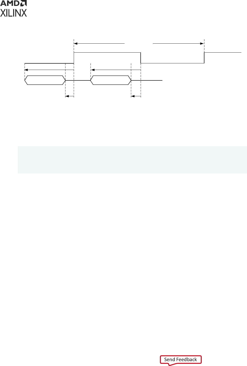
Figure 57: Output Delay Example 3
Data Rising Edge Data Falling Edge
Forward clock
clk_ddr
Period = 6 ns
1.1 ns0.9 ns
2.1 ns 1.9 ns
X25393-060321
Output Delay Example Four
This example species the clock and output delay on the STARTUPE3 internal pins (UltraScale+
devices) to me the paths from the fabric to STARTUPE3.
> create_generated_clock -name clk_sck -source [get_pins -hierarchical
*axi_quad_spi_0/ext_spi_clk] [get_pins STARTUP/CCLK] -edges {3 5 7}
> set_output_delay -clock clk_sck -max 6 [get_pins STARTUP/DATA_OUT[*]]
> set_output_delay -clock clk_sck -min 1 [get_pins STARTUP/DATA_OUT[*]]
For more informaon on ming constraints for STARTUPE3, refer to the AXI Quad SPI LogiCORE
IP Product Guide (PG153).
Chapter 4: Constraining I/O Delay
UG903 (v2022.1) June 1, 2022 www.xilinx.com
Using Constraints 105
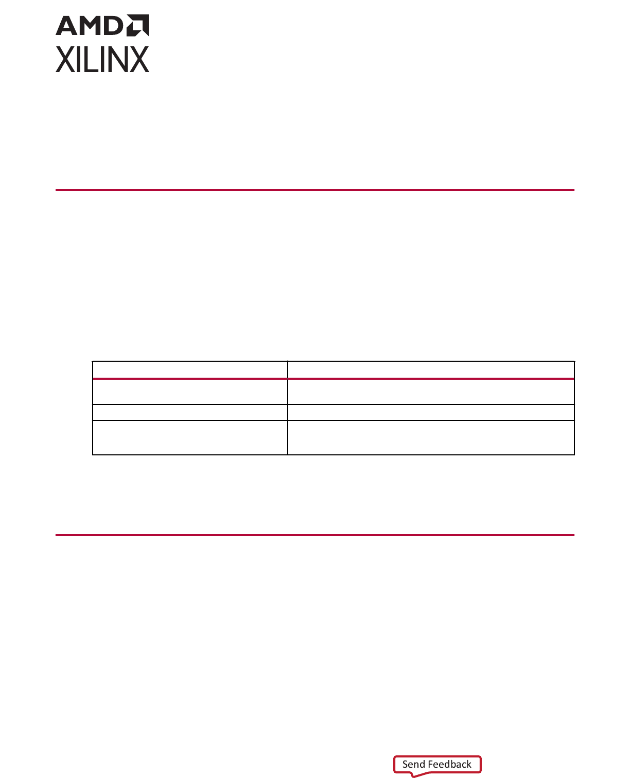
Chapter 5
Timing Exceptions
About Timing Exceptions
A ming excepon is needed when the logic behaves in a way that is not med correctly by
default. You must use a ming excepon command any me you want the ming handled
dierently (for example, for logic that only has the result captured every other clock cycle by
design).
The Xilinx
®
Vivado
®
IDE supports the ming excepons commands shown in the following table:
Table 6: Timing Exceptions Commands
Command Function
set_multicycle_path Indicates the number of clock cycles required to propagate data from
the start to the end of a path.
set_false_path Indicates that a logic path in the design should not be analyzed.
set_max_delay set_min_delay Sets the minimum and maximum path delay value. This overrides the
default setup and hold constraints with user specified maximum and
minimum delay values.
Note: For runme consideraon, Vivado tools do not provide on-the-y analysis for conicng ming
excepons. Run report_exceptions for full analysis and reporng of the ming excepons. For more
informaon, refer to Vivado Design Suite User Guide: Design Analysis and Closure Techniques (UG906).
Multicycle Paths
The Mulcycle Path constraint allows you to modify the setup and hold relaonships determined
by the mer, based on the design clock waveforms. By default, the Vivado IDE ming engine
performs a single-cycle analysis. This analysis can be too restricve, and can be inappropriate for
certain logic paths.
The most common example is the logical path that requires more than one clock cycle for the
data to stabilize at the endpoint. If the control circuitry of the path startpoint and endpoint allows
it, Xilinx recommends that you use the Mulcycle Path constraint to relax the setup requirement.
Chapter 5: Timing Exceptions
UG903 (v2022.1) June 1, 2022 www.xilinx.com
Using Constraints 106

The hold requirement might sll maintain the original relaonship, depending on your intent. This
helps the ming-driven algorithms to focus on other paths that have ghter requirements and
that are challenging. It can also help in reducing runme.
Setting the Path Multipliers and Clock Edges
The set_multicycle_path command is used to modify the path requirement mulpliers (for
setup analysis, hold analysis, or both) with respect to the source clock or the desnaon clock.
set_multicycle_path Syntax
The syntax of the set_mulcycle_path command with the basic opons is:
set_multicycle_path <path_multiplier> [-setup|-hold] [-start|-end]
[-from <startpoints>] [-to <endpoints>] [-through <pins|cells|nets>]
You must specify the <path_multiplier>. The default values used by the mer are:
• 1 for setup analysis (or recovery)
• 0 for hold analysis (or removal)
The hold relaonship is ed to the setup relaonship. Use the following formula to retrieve the
number of hold cycles for most common cases:
Hold cycles = <setup path multiplier> - 1 - <hold path multiplier>
• By default, the setup path mulplier is dened with respect to the desnaon clock. To
modify the setup requirement with respect to the source clock, use the -start opon.
• Similarly, the hold path mulplier is dened with respect to the source clock. To modify the
hold requirement with respect to the desnaon clock, use the -end opon.
Note: For a denion of the relevant terms, see this link in the Vivado Design Suite User Guide: Design
Analysis and Closure Techniques (UG906).
IMPORTANT!
There are two hold relaonships for each setup relaonship. (1) The rst hold relaonship
ensures that the setup launch edge is not captured by the edge arriving before the acve capture edge. (2)
The second hold relaonship ensures that the edge aer the acve launch edge is not captured by the
acve capture edge. The ming analysis tool calculates both hold relaonships but only the most
restricve is kept during analysis and reporng. See the following gure.
Chapter 5: Timing Exceptions
UG903 (v2022.1) June 1, 2022 www.xilinx.com
Using Constraints 107
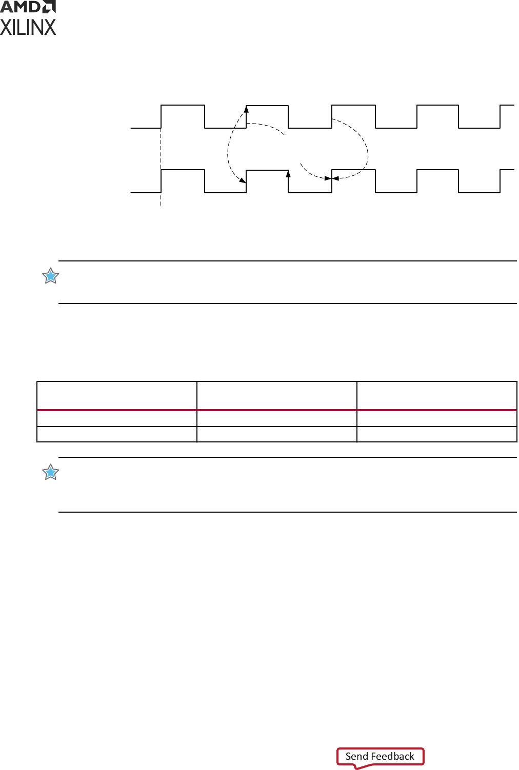
Figure 58: Example of Setup and Hold Relationships for a Path
Source Clock
Hold
Relationship 1
Setup
Relationship
Hold
Relationship 2
0ns 2ns 4ns 6ns 8ns 10ns 12ns
Destination Clock
capture edge
launch edge
X14346-061015
IMPORTANT! The
-start
and
-end
opons have no apparent eect when applying a Mulcycle Path
constraint on paths clocked by the same clock or clocked by two idencal clocks (that is, when the clocks
have the same waveform with or without a phase shi).
The following table summarizes how the acve launch and capture edges are aected by the -
start and -end opons.
Table 7: Active Launch and Capture Edges
Source Clock (-start) Moves the
launch edge
Destination Clock (-end) Moves
the capture edge
Setup <---- (backward) ----> (forward) (default)
Hold ----> (forward) (default) <---- (backward)
IMPORTANT! The
-setup
opon of the
set_multicycle_path
command does not only modify
the setup relaonship. It also aects the hold relaonships which are always ed to the setup
relaonships. If the hold relaonship is to be restored back to its original posion, another
set_multicycle_path
specicaon would be needed with
-hold
.
Note: A Mulcycle constraint can be set on a single path, on mulple paths, or even between two clocks.
The following secons cover the common Mulcycle Path constraint scenarios and illustrate the
impact of the setup and hold mulpliers and the -start and -end opons on the ming path
requirement.
Multicycles in Single Clock Domain
A Mulcycle constraint dened within the same clock domain or between two clocks with the
same waveform (no phase-shi) works the same way. See the following gure.
Chapter 5: Timing Exceptions
UG903 (v2022.1) June 1, 2022 www.xilinx.com
Using Constraints 108
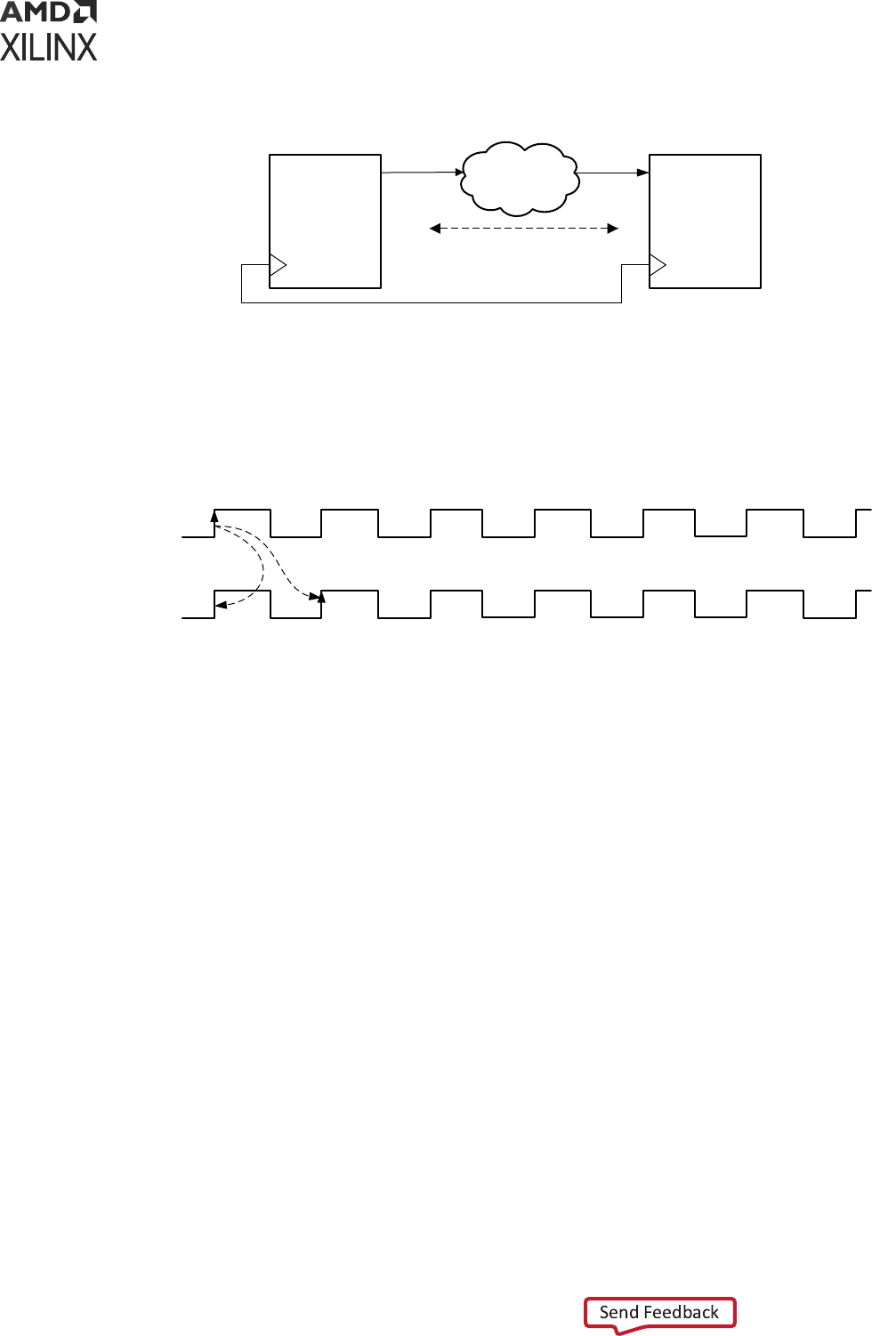
Figure 59: Multicycle Constraint in Single Clock Domain
DATAPATH
Q
REGISTER
Q
REGISTER
N Cycles
CLK CLK
X16808-041716
The default Setup and Hold relaonships that are resolved by the Stac Timing Analysis (STA)
tool are shown in the following gure.
Figure 60: Default Setup and Hold Relationships
Destination
clock (CLK2)
Source clock
(CLK1)
launch edge
capture edge
Setup
Hold
0ns 2ns 4ns 6ns 8ns 10ns 12ns 14ns 16ns 18ns 20ns 22ns 24ns
X14347-061015
The Setup and Hold ming requirements are:
• Setup check
T
Datapath(max)
< TCLK
(t=Period)
- T
Setup
• Hold check
T
Datapath(min)
> TCLK
(t=0)
+ T
Hold
Relaxing Setup While Maintaining Hold
The following gure shows a path between two ip-ops that are enabled every two cycles. It is
safe to dene a Mulcycle Path constraint on this path to indicate that the rst edge of the
desnaon clock is not acve, and only the second edge of the desnaon clock will capture a
new data.
Chapter 5: Timing Exceptions
UG903 (v2022.1) June 1, 2022 www.xilinx.com
Using Constraints 109
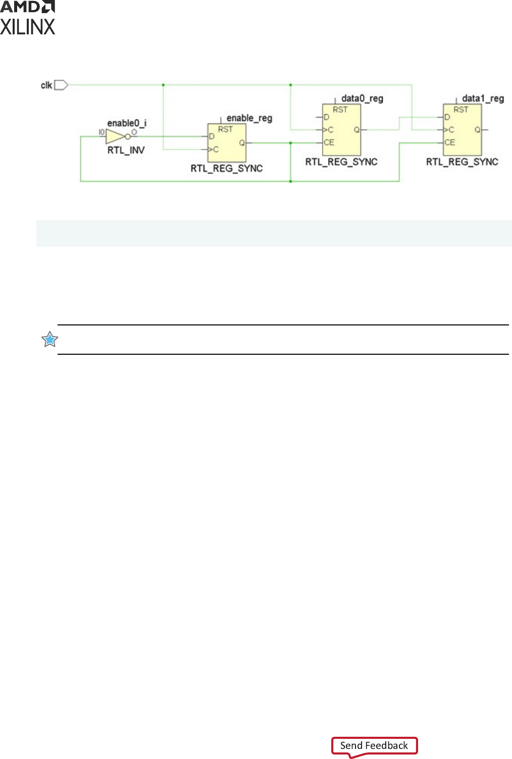
Figure 61: Registers Enabled Every Two Cycles
The following constraint establishes a new setup relaonship:
set_multicycle_path 2 -setup -from [get_pins data0_reg/C] -to [get_pins
data1_reg/D]
This link in the Vivado Design Suite User Guide: Design Analysis and Closure Techniques (UG906)
describes how the hold relaonships are derived from the setup relaonships. When modifying
the setup relaonship, the hold relaonships are also modied to follow the changes in the setup
launch and capture edges.
IMPORTANT! If the new hold requirements become too aggressive, it will likely result in dicult ming
closure. It is the your responsibility to relax the hold requirement assuming it is safe for the design.
In the same example as Figure 61, aer moving the setup check to the second capture edge, the
hold check is automacally moved to the rst capture edge (that is, one clock period before the
setup check).
The following gure shows how both the setup and hold relaonships have changed when only
the setup path mulplier has been dened with the Mulcycle Path constraint.
Chapter 5: Timing Exceptions
UG903 (v2022.1) June 1, 2022 www.xilinx.com
Using Constraints 110
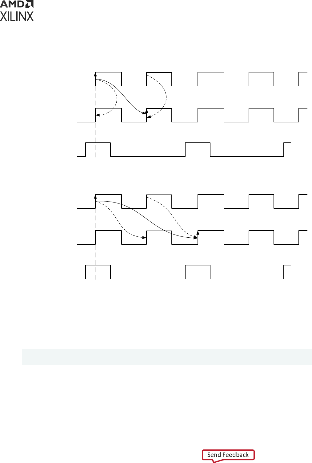
Figure 62: Multicycle Path: Relaxing Setup Only
Source clock
Destination clock
Clock Enable
0ns
launch edge
capture edge
Hold
HoldSetup
Source clock
Destination clock
Clock Enable
0ns 2ns 4ns 6ns 8ns 10ns 12ns
launch edge
capture edge
Hold HoldSetup
AFTER
BEFORE
X14377-120415
Holding the data in the data0_reg for one cycle is not needed for this path to be funconal due
to the clock enable. In this case, Xilinx recommends changing the hold relaonship back to the
original, which is between the same launch and capture edges. To do so, you must add a second
Mulcycle Path constraint that modies the hold check only:
set_multicycle_path 1 -hold -end -from [get_pins data0_reg/C] \
-to [get_pins data1_reg/D]
The -end opon is used with set_multicycle -hold command because the edges of the
capture clock must be moved backward.
Note: Because the launch and capture clocks have the same waveforms, the -end opon is oponal.
Moving the capture edges backward result in the same hold relaonship as moving the launch edges
forward. To simplify the expressions, the -end opon has been removed from the next two examples.
Chapter 5: Timing Exceptions
UG903 (v2022.1) June 1, 2022 www.xilinx.com
Using Constraints 111
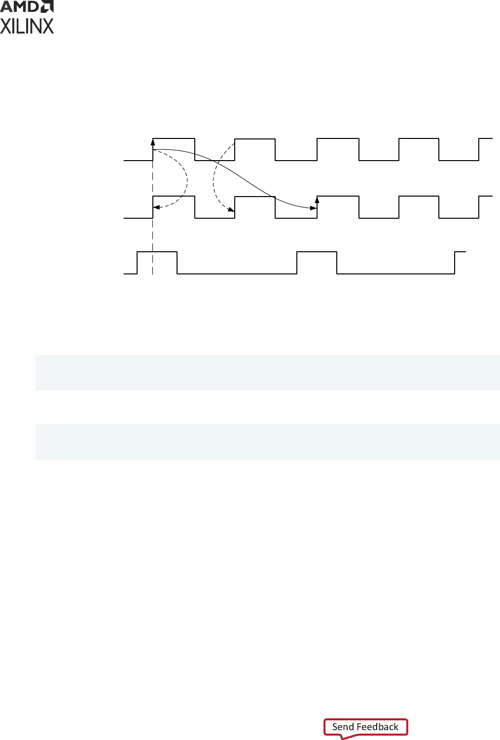
The following gure shows the updated setup and hold relaonships aer applying both
Mulcycle Path constraints.
Figure 63: Multicycle Path: Relaxing Setup and Hold
Source clock
Destination clock
Clock Enable
0ns 2ns 4ns 6ns 8ns 10ns 12ns
launch edge
capture edge
Hold
Hold
Setup
X14348-120415
To summarize this example, the following constraints are necessary to properly dene a
mulcycle path of two (2) between data0_reg/C and data1_reg/D:
set_multicycle_path 2 -setup -from [get_pins data0_reg/C] -to [get_pins
data1_reg/D] set_multicycle_path 1 -hold -from [get_pins data0_reg/C] -to
[get_pins data1_reg/D]
For a mulcycle with a setup mulplier of four (4), the constraints are:
set_multicycle_path 4 -setup -from [get_pins data0_reg/C] -to [get_pins
data1_reg/D] set_multicycle_path 3 -hold -from [get_pins data0_reg/C] -to
[get_pins data1_reg/D]
Chapter 5: Timing Exceptions
UG903 (v2022.1) June 1, 2022 www.xilinx.com
Using Constraints 112
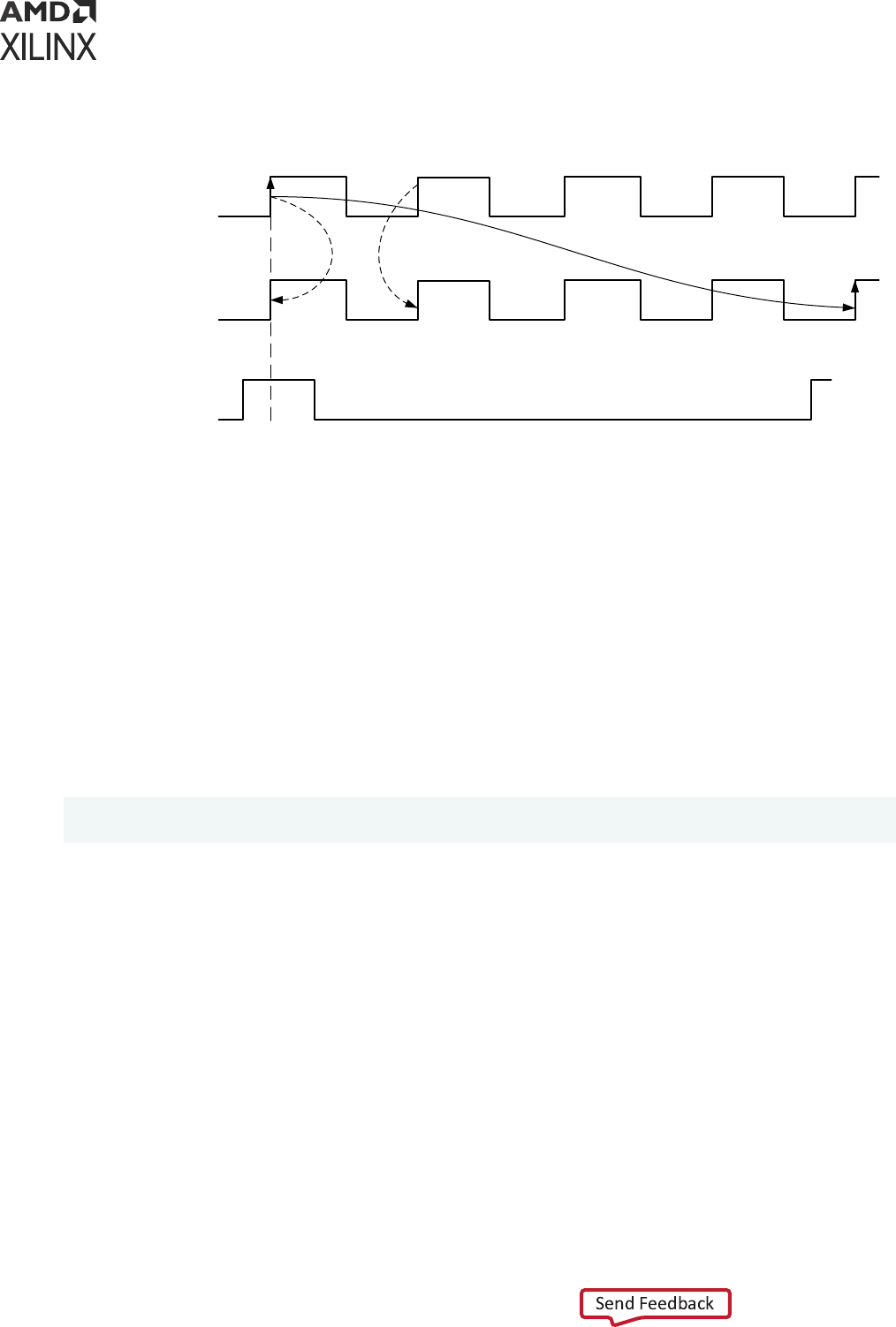
Figure 64: Multicycle Path with Setup Multiplier of Four (4)
Source clock
Destination clock
Clock Enable
0ns 2ns 4ns 6ns 8ns 10ns 12ns
launch edge
capture edge
Hold
Hold
Setup
X14349-120415
Moving the Setup
The following examples show the results of moving the setup:
• Example One: Setup=5 / Hold Moved Accordingly
• Example Two: Setup=5 / Hold=4
Example One: Setup=5 / Hold Moved Accordingly
Let’s assume that the setup path mulplier is set to ve (5). Because the hold path mulplier is
not specied, the hold relaonship is derived from the setup launch and capture edges:
set_multicycle_path 5 -setup -from [get_pins data0_reg/C] -to [get_pins
data1_reg/D]
By default, the setup mulplier is applied against the capture clock. This results in moving the
edge on the capture clock forward. The setup capture edge comes aer ve clock periods instead
of just one. Because no hold mulplier has been specied, the edge of the capture clock used for
the hold check stays the edge that arrives one cycle before the acve edge used for the setup
check.
The edges on the launch clock do not change for the setup and hold relaonships.
Chapter 5: Timing Exceptions
UG903 (v2022.1) June 1, 2022 www.xilinx.com
Using Constraints 113
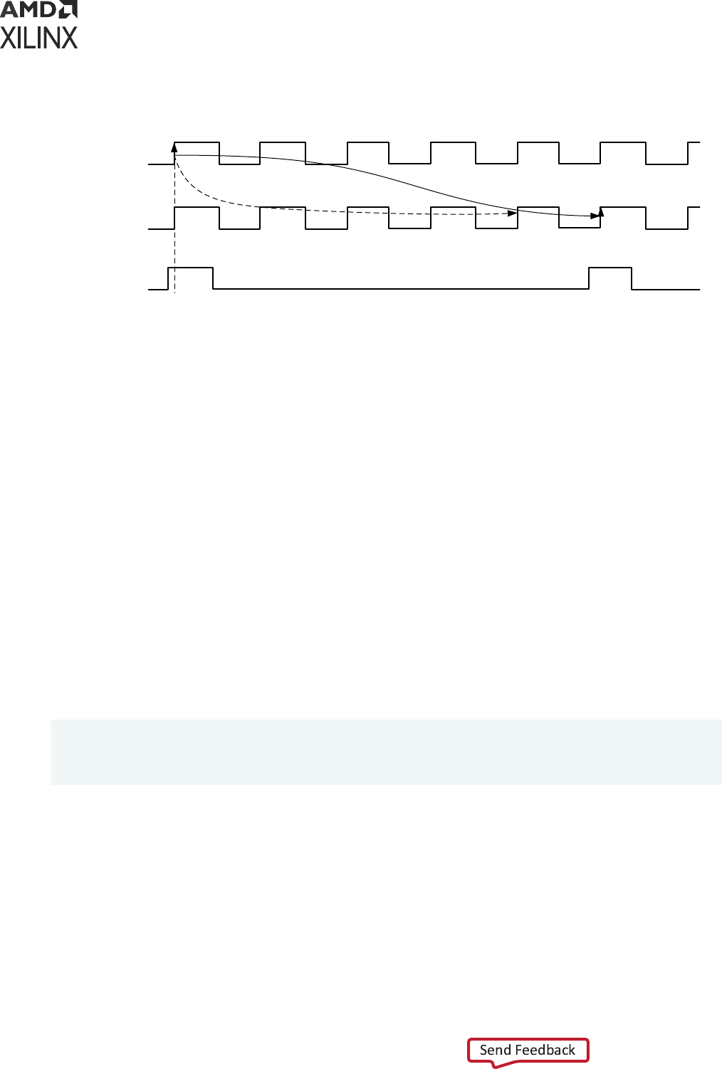
Figure 65: Setup=5, Hold Moved Accordingly
launch edge
capture edge
Setup
Hold
0ns 2ns 4ns 6ns 8ns 10ns 12ns 14ns 16ns 18ns 20ns 22ns 24ns
Clock Enable
X14350-120415
Destination
clock (CLK2)
Source clock
(CLK1)
With a four-cycle hold requirement, the ming-driven implementaon tools usually have to
insert a large amount of delay in the datapath in order to meet hold ming in both Slow and Fast
ming corners. This results in unnecessary area and power consumpon. For this reason, it is
important to relax the hold requirement when possible.
In this example design, the clock enable signal provides the safety to not have to hold the data in
the data0_reg for four cycles without risking metastability. Example Two: Setup=5 / Hold=4
describes how the hold requirement can be relaxed.
Example Two: Setup=5 / Hold=4
This example assumes that the following are dened:
• A setup mulplier of ve (5)
• A hold mulplier of four (4) (that is, 5-1)
This corresponds to a transfer between two sequenal cells when a new data is launched and
captured every ve (5) cycles.
set_multicycle_path 5 -setup -from [get_pins data0_reg/C] -to [get_pins
data1_reg/D]
set_multicycle_path 4 -hold -from [get_pins data0_reg/C] -to [get_pins
data1_reg/D]
By default, the setup mulplier is applied against the desnaon clock, which in this case results
in moving the capture edge forward to the h cycle instead of the rst cycle.
Accordingly, by default, the hold check follows the setup check.
On specifying the second command, the hold mulplier is applied against the source clock, which
in this case results in moving the launch edge forward to the fourth cycle.
Chapter 5: Timing Exceptions
UG903 (v2022.1) June 1, 2022 www.xilinx.com
Using Constraints 114
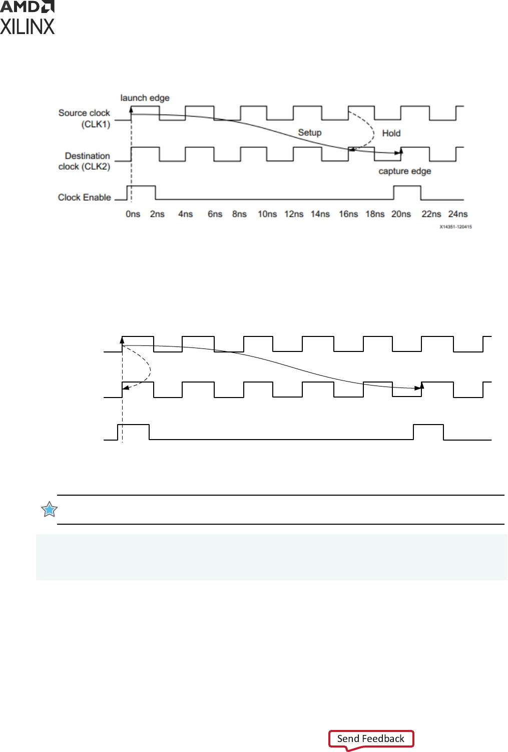
Figure 66: Setup=5, Hold=4
Because both source and desnaon clocks have the same waveforms, and are phase-aligned,
Figure 66 is equivalent to Figure 67.
Figure 67: Setup=5, Hold=4
launch edge
capture edge
Setup
Hold
0ns 2ns 4ns 6ns 8ns 10ns 12ns 14ns 16ns 18ns 20ns 22ns 24ns
Clock Enable
X14352-120415
Destination
clock (CLK2)
Source clock
(CLK1)
IMPORTANT! In general, within a clock domain or between two clocks with the same waveform, when a
setup mulplier of N is dened, dene a hold mulplier of N-1 (most common case) as shown below.
set_multicycle_path N -setup -from [get_pins data0_reg/C] -to [get_pins
data1_reg/D]
set_multicycle_path N-1 -hold -from [get_pins data0_reg/C] -to [get_pins
data1_reg/D]
Chapter 5: Timing Exceptions
UG903 (v2022.1) June 1, 2022 www.xilinx.com
Using Constraints 115
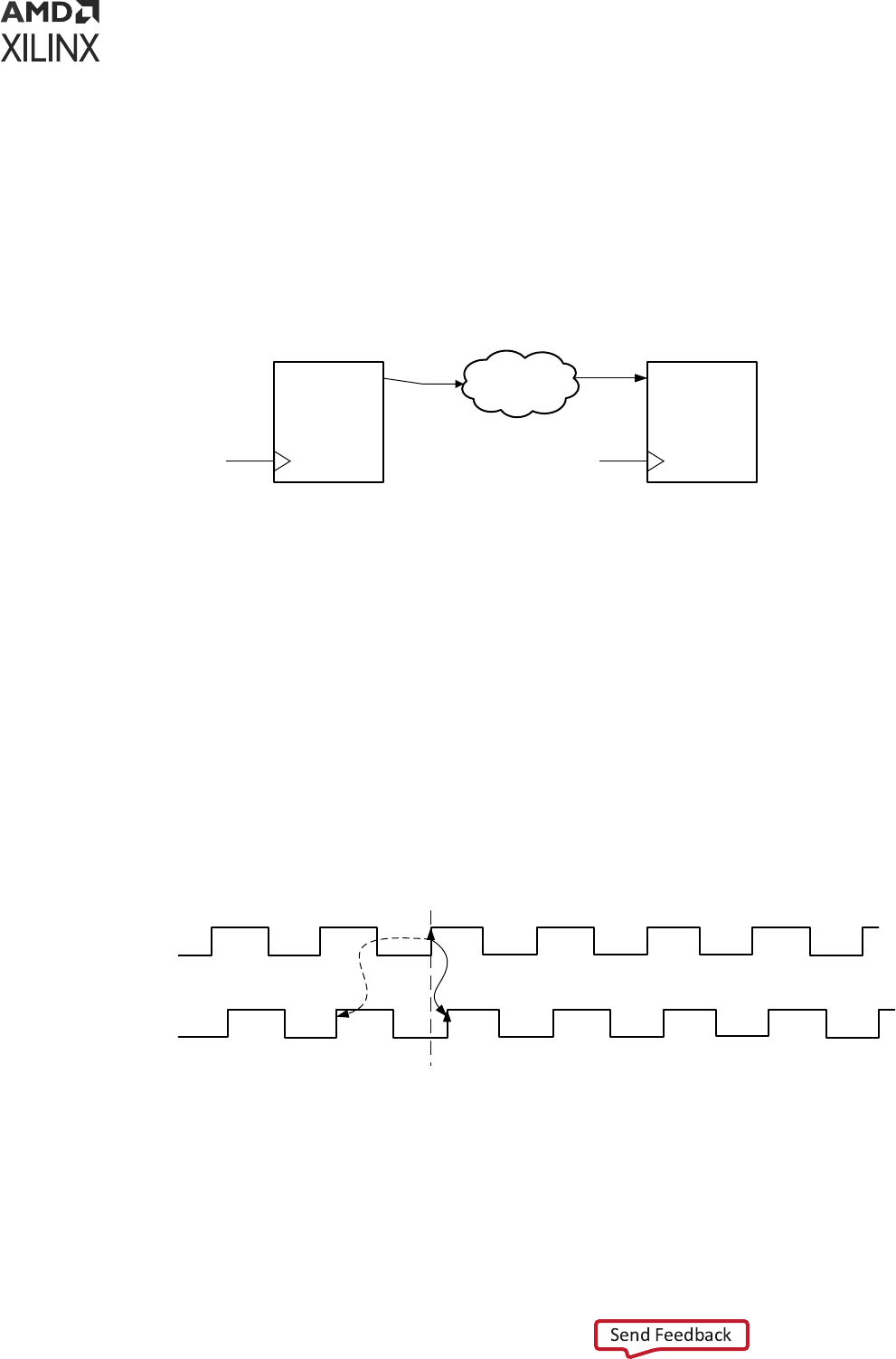
Multicycle Paths and Clock Phase-Shift
Somemes a ming constraint must be dened between two clock domains that have the same
clock period, but a phase-shi between the two clocks. In those cases, it is crical to understand
the default setup and hold relaonships used by the ming engine. If not carefully adjusted, the
phase-shi between two clocks might result in over constraining the logic between the two clock
domains.
Figure 68: Multicycle Paths and Clock Phase-Shift
DATAPATH
Q
REGISTER
Q
REGISTER
CLK1 CLK2
X16810-041716
For example, assume the following:
• The two clocks CLK1 and CLK2 have the same waveform.
• CLK2 is shied by +0.3 ns.
The setup relaonship is calculated by the ming engine by looking at all the edges on both
waveforms and selecng the two edges on the launch and capture clocks that result in the
stricter constraint.
Because of the clocks phase-shi, the setup and hold relaonships used by the ming engine
might not be those expected. See the following gure.
Figure 69: Default Scenario of Phase-Shift Without Multicycle Path
launch edge
capture edge
Setup
Hold
0ns 2ns 4ns 6ns 8ns 10ns 12ns 14ns 16ns-2ns-4ns-6ns-8ns
X14353-120415
Destination
clock (CLK2)
Source clock
(CLK1)
In this example, the setup constraint due to the phase-shi is 0.3 ns. This makes it almost
impossible to achieve ming closure. On the other hand, the hold check is -3.7 ns, which is too
lenient.
Chapter 5: Timing Exceptions
UG903 (v2022.1) June 1, 2022 www.xilinx.com
Using Constraints 116
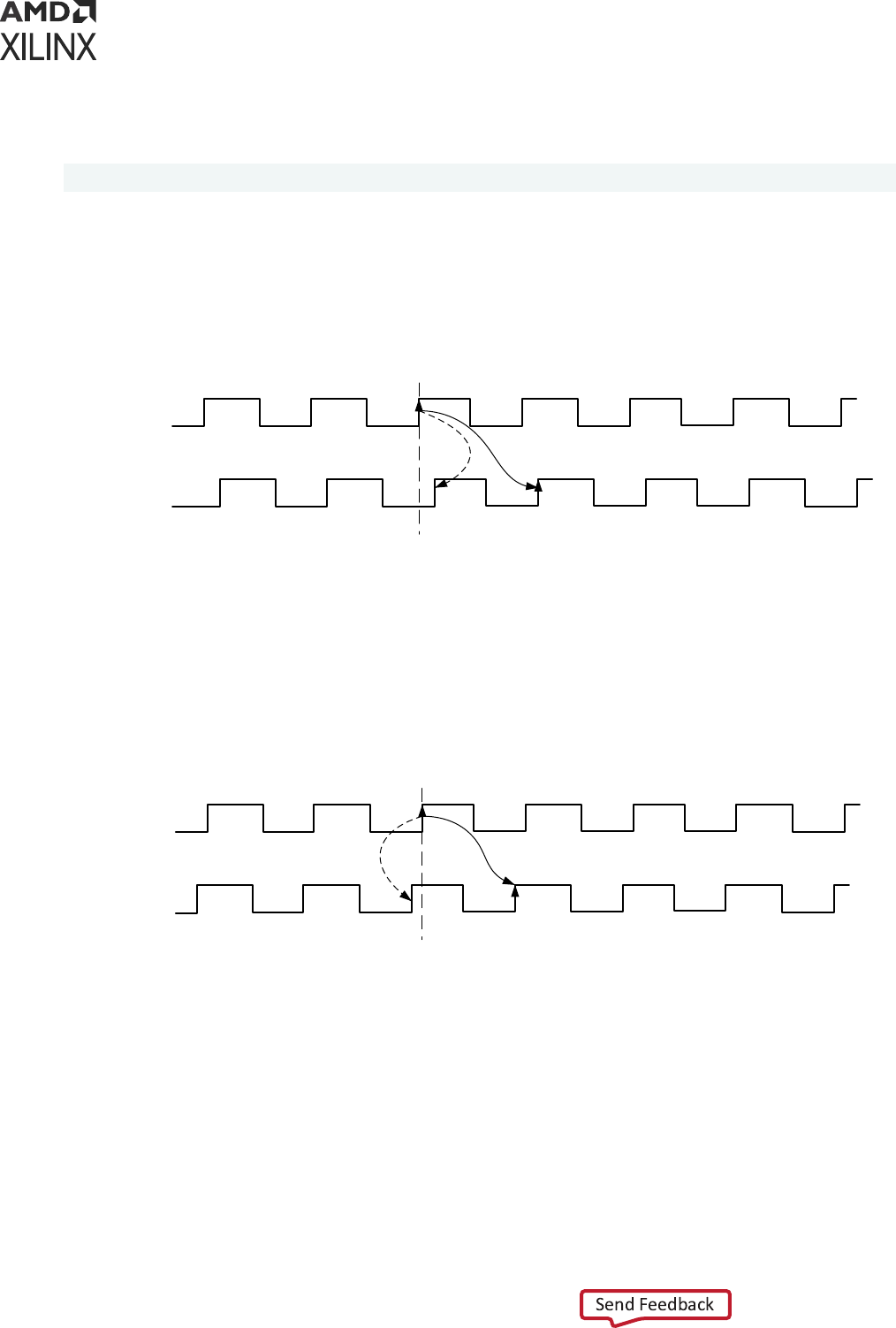
The setup and hold edges must be adjusted to match your intent. This is done by adding a
Mulcycle constraint with a setup mulplier of two (2):
set_multicycle_path 2 -setup -from [get_clocks CLK1] -to [get_clocks CLK2]
This results in moving the capture edge for the setup requirement forward by one cycle. The
default edge for the hold is derived from the setup requirement. It does not need to be specied.
Figure 70: Default Scenario of Positive Phase-Shift: Setup 2 (-end), Hold Moved
Accordingly
launch edge
capture edge
SetupHold
0ns 2ns 4ns 6ns 8ns 10ns 12ns 14ns 16ns-2ns-4ns-6ns-8ns
X14354-120415
Destination
clock (CLK2)
Source clock
(CLK1)
In the case of negave phase-shi, as shown in the following gure, between the two clock
domains, the launch and capture edges used for the setup and hold checks are similar to those
from the previous secon (single clock domain, no phase-shi).
Figure 71: Default Scenario of Negative Phase-Shift
launch edge
capture edge
Setup
Hold
0ns 2ns 4ns 6ns 8ns 10ns 12ns 14ns 16ns-2ns-4ns-6ns-8ns
X14355-120415
Destination
clock (CLK2)
Source clock
(CLK1)
For a negave phase-shi, a Mulcycle constraint is typically not needed to counter-balance the
eect of the phase-shi. An excepon occurs if the phase-shi is so large that the clock launch
or capture edges must be adjusted to keep realisc setup and hold requirements.
Multicycles Between SLOW-to-FAST Clocks
In this scenario, the launch clock CLK1 is the slow clock; the capture clock CLK2 is the fast clock.
See the following gure.
Chapter 5: Timing Exceptions
UG903 (v2022.1) June 1, 2022 www.xilinx.com
Using Constraints 117
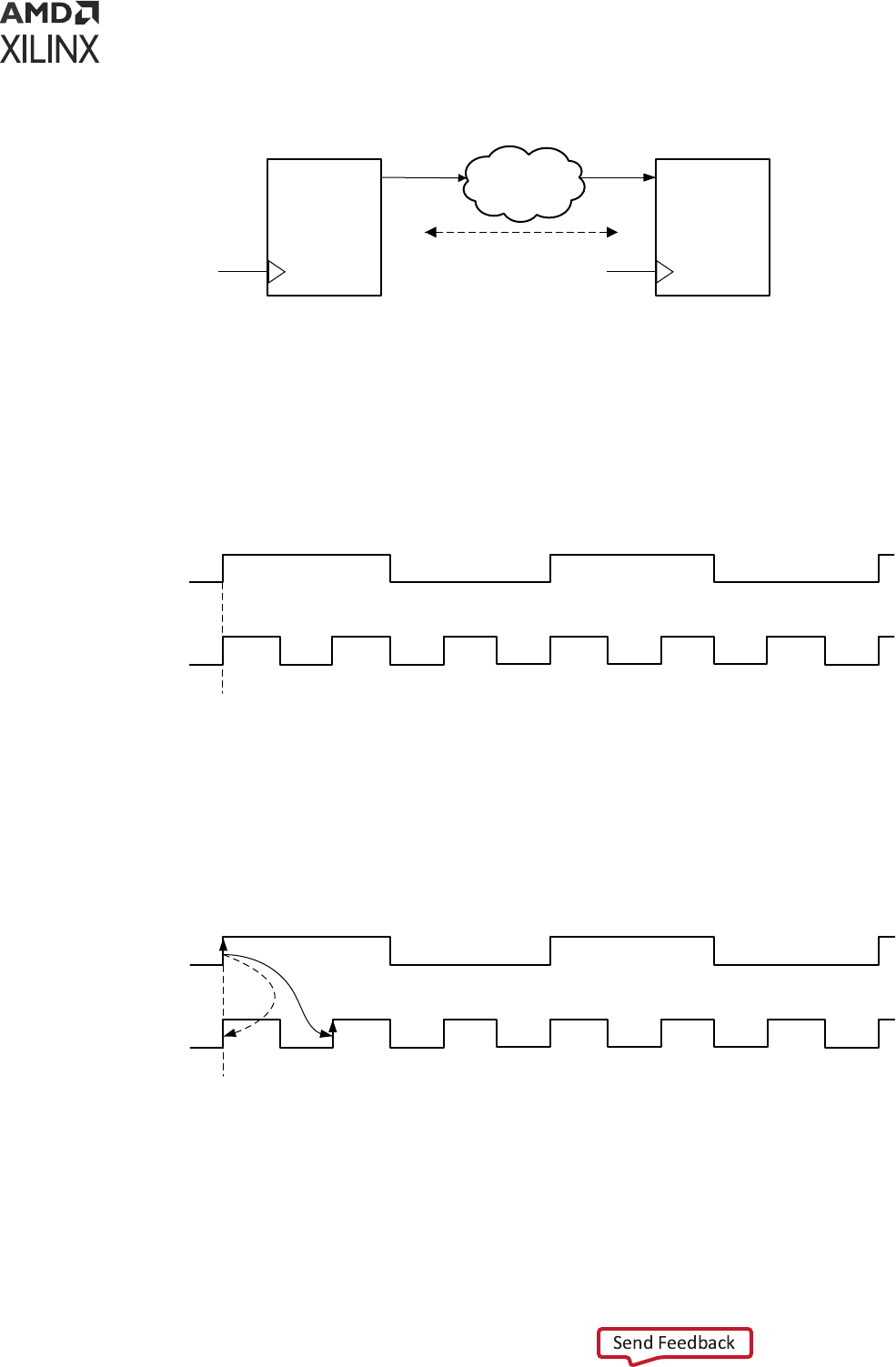
Figure 72: Multicycles Between SLOW-to-FAST Clocks
DATAPATH
Q
REGISTER
Q
REGISTER
CLK1
(SLOW)
CLK2
(FAST)
N Cycles
X16809-041716
For example, assume the following:
• CLK2 is three mes the frequency of CLK1.
• A clock enable signal on the receiving registers allows a Mulcycle constraint to be set
between both clocks. See the following gure.
Figure 73: Multicycles Between SLOW-to-FAST Clocks
0ns 2ns 4ns 6ns 8ns 10ns 12ns 14ns 16ns 18ns 20ns 22ns 24ns
X14356-120415
Destination
clock (CLK2)
Source clock
(CLK1)
The setup and hold relaonships that are resolved by the STA tool when no mulcycle is applied
are shown in the following gure.
Figure 74: Default Setup and Hold Relationships
0ns 2ns 4ns 6ns 8ns 10ns 12ns 14ns 16ns 18ns 20ns 22ns 24ns
launch edge
capture edge
SetupHold
X14357-120415
Destination
clock (CLK2)
Source clock
(CLK1)
Chapter 5: Timing Exceptions
UG903 (v2022.1) June 1, 2022 www.xilinx.com
Using Constraints 118
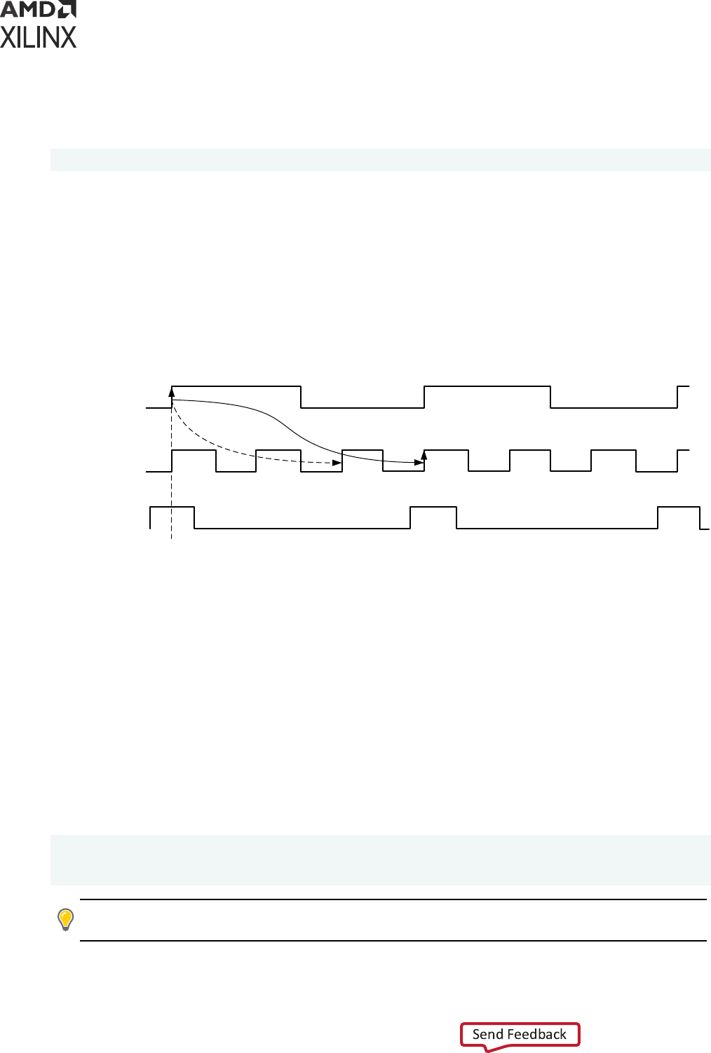
Example One: Setup=3 / Hold Moved Accordingly
For example, assume that only a setup mulplier of three (3) is dened.
set_multicycle_path 3 -setup -from [get_clocks CLK1] -to [get_clocks CLK2]
The consequence of the setup mulplier is to move the edge of the capture clock used for setup
check forward by two (2) cycles (that is, 3-1 cycles). Because no hold mulplier has been
specied, the hold relaonship is derived by the tool from the setup launch and capture edges.
The launch clock acve edge is not modied by the Mulcycle constraint.
The setup and hold relaonships aer the mulcycle are shown in the following gure:
Figure 75: Setup=3, Hold Moved Accordingly
Destination
clock (CLK2)
Source clock
(CLK1)
0ns 2ns 4ns 6ns 8ns 10ns 12ns 14ns 16ns 18ns 20ns 22ns 24ns
launch edge
capture edge
SetupHold
Source clock
(CLK2)
X14358-120415
There is no need to hold the data in the launch registers for one cycle of CLK2 for this path to be
funconal. Doing so adds unnecessary logic, which increases area and consumes power.
Because the receiving registers have a clock enable signal, it is safe to relax the hold requirement
without risks of metastability.
Example Two: Setup=3 / Hold=2 (-end)
To relax the hold requirement for the previous example, the capture clock edge for the hold
relaonship must be moved backward by two (2) clock cycles. This is done by specifying the -
end opon with the set_multicycle_path -hold command:
set_multicycle_path 3 -setup -from [get_clocks CLK1] -to [get_clocks CLK2]
set_multicycle_path 2 -hold -end -from [get_clocks CLK1] -to [get_clocks
CLK2]
TIP:
If
-end
is not specied with
set_multicycle_path -hold
, then the launch clock edge is
instead moved forward. This does not result in the intended hold requirement.
Chapter 5: Timing Exceptions
UG903 (v2022.1) June 1, 2022 www.xilinx.com
Using Constraints 119
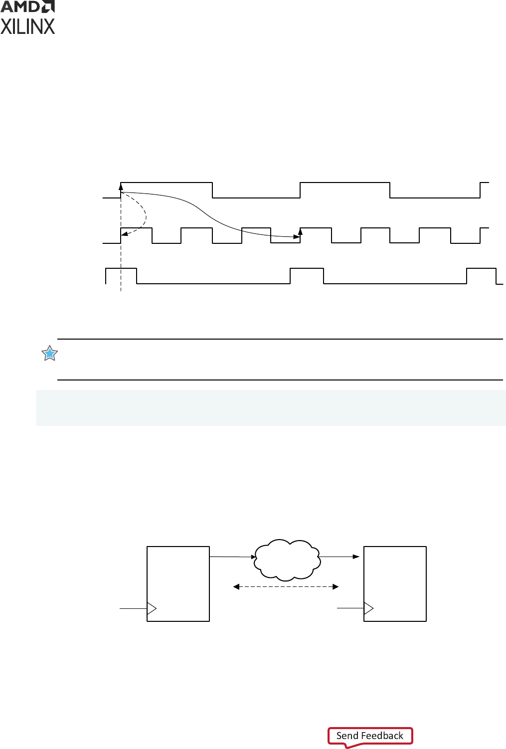
As in Example One: Setup=3 / Hold Moved Accordingly, the setup mulplier moves the edge of
the capture clock used for setup check forward by two (2) cycles (that is, 3-1 cycles).
The setup and hold relaonships aer the two Mulcycle constraints are shown in the following
gure.
Figure 76: Setup=3, Hold=2 (-end)
Destination
clock (CLK2)
Source clock
(CLK1)
0ns 2ns 4ns 6ns 8ns 10ns 12ns 14ns 16ns 18ns 20ns 22ns 24ns
launch edge
capture edge
SetupHold
Source clock
(CLK2)
X14359-120415
IMPORTANT! For a SLOW-to-FAST clock domain crossing, when a setup mulplier of N is dened, dene
a hold mulplier of N-1 against the capture clock (-end) (most common case) as shown in the following
code example.
set_multicycle_path N -setup -from [get_clocks CLK1] -to [get_clocks CLK2]
set_multicycle_path N-1 -hold -end -from [get_clocks CLK1] -to [get_clocks
CLK2]
Multicycles Between FAST-to-SLOW Clocks
In the following scenario, the launch clock CLK1 is the fast clock and the capture clock CLK2 is
the slow clock. See the following gure.
Figure 77: Multicycles Between FAST-to-SLOW Clocks
DATAPATH
Q
REGISTER
Q
REGISTER
CLK1
(FAST)
CLK2
(SLOW)
N Cycles
X16811-041716
In the next example, the launch clock CLK1 is the fast clock. The capture clock CLK2 is the slow
clock. Assume that CLK1 is three (3) mes the frequency of CLK2. See the following gure.
Chapter 5: Timing Exceptions
UG903 (v2022.1) June 1, 2022 www.xilinx.com
Using Constraints 120
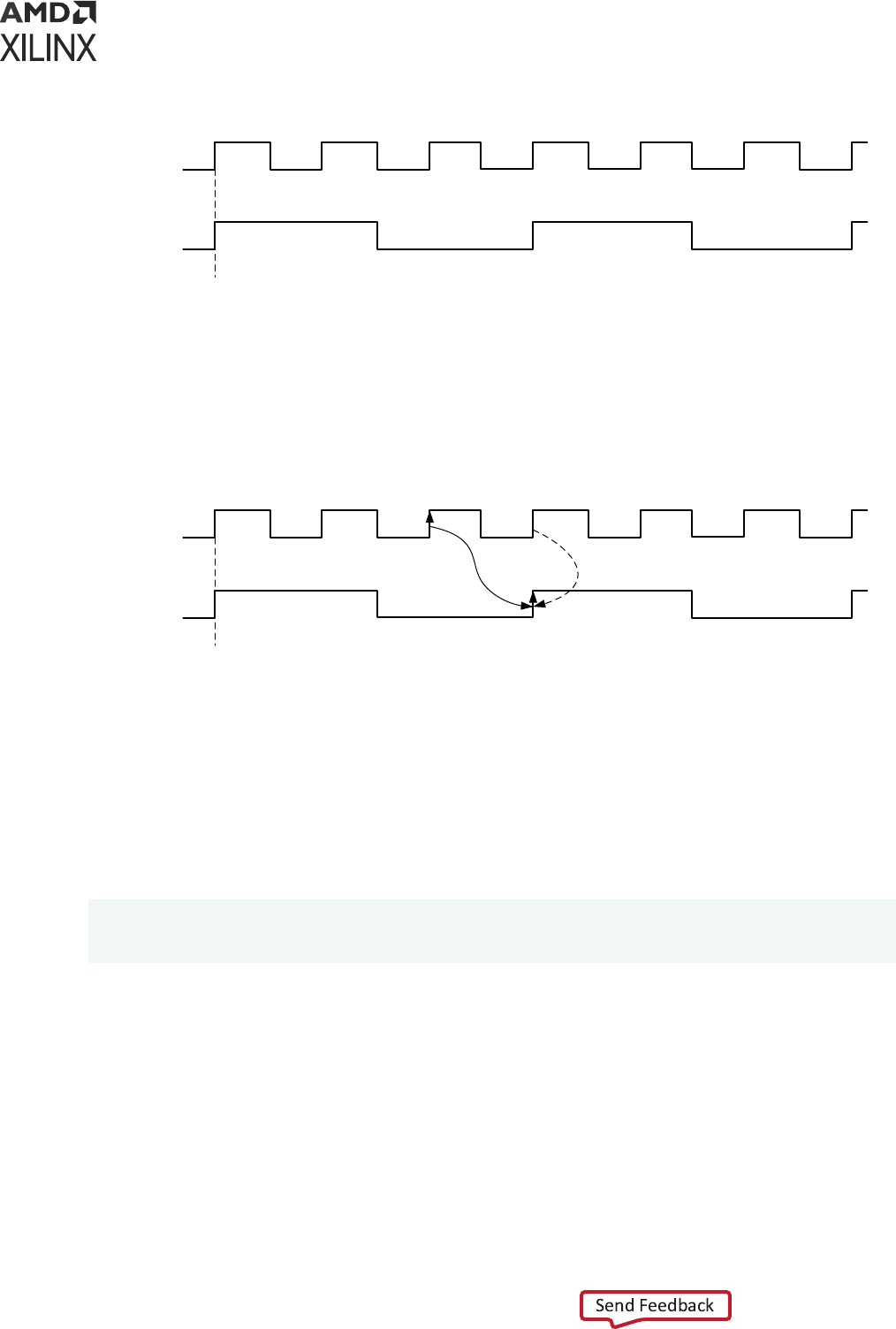
Figure 78: Multicycles Between FAST-to-SLOW Clocks
0ns 2ns 4ns 6ns 8ns 10ns 12ns 14ns 16ns 18ns 20ns 22ns 24ns
X14360-120415
Destination
clock (CLK2)
Source clock
(CLK1)
The setup and hold relaonships that are resolved by the STA tool when no mulcycle is applied
are shown in the following gure:
Figure 79: Default Setup and Hold Relationships
0ns 2ns 4ns 6ns 8ns 10ns 12ns 14ns 16ns 18ns 20ns 22ns 24ns
launch edge
capture edge
HoldSetup
X14361-120415
Destination
clock (CLK2)
Source clock
(CLK1)
Example: Setup=3 (-start) / Hold=2
This example assumes the following:
• A setup mulplier of three (3) is dened against the launch clock (-start).
• A hold mulplier of one (1) is dened. Example:
set_multicycle_path 3 -setup -start -from [get_clocks CLK1] -to
[get_clocks CLK2]
set_multicycle_path 2 -hold -from [get_clocks CLK1] -to [get_clocks CLK2]
The consequence of dening the setup mulplier against the launch clock (-start) is to move
the edge of the launch clock used for setup check backward by two (2) cycles (that is, 3-1 cycles).
However, because a hold mulplier is dened against the launch clock (default -start opon
with -hold), the edge of the launch clock that is used for the hold relaonship is moved forward
by two (2) cycles.
For both setup and hold checks, the capture clock edge does not change. See the following
gure.
Chapter 5: Timing Exceptions
UG903 (v2022.1) June 1, 2022 www.xilinx.com
Using Constraints 121
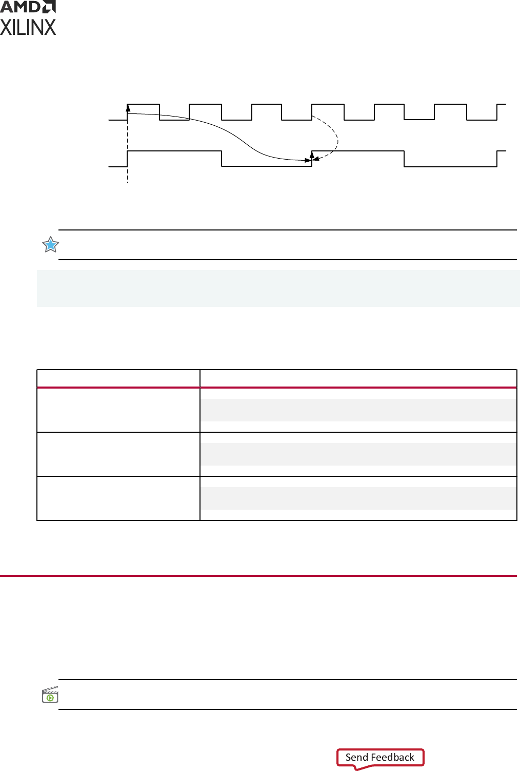
Figure 80: Setup=3 (-start), Hold=2
Destination
clock (CLK2)
Source clock
(CLK1)
0ns 2ns 4ns 6ns 8ns 10ns 12ns 14ns 16ns 18ns 20ns 22ns 24ns
launch edge
capture edge
HoldSetup
X14362-120415
IMPORTANT! For a FAST-to-SLOW clock domain crossing, dene a setup mulplier of N against the
launch clock (-start) with a hold mulplier of N-1 (most common case). See the following example:
set_multicycle_path N -setup -start -from [get_clocks CLK1] -to [get_clocks
CLK2]
set_multicycle_path N-1 -hold -from [get_clocks CLK1] -to [get_clocks CLK2]
The following table summarizes the previous results.
Table 8: To define a multicycle path with a Setup of N
Scenario Multicycle Constraints
Same clock domain or between
synchronous clock domains with same
period and no phase-shift
set_multicycle_path N -setup -from CLK1 -to CLK2
set_multicycle_path N-1 -hold -from CLK1 -to CLK2
Between SLOW-to FAST synchronous
clock domains
set_multicycle_path N -setup -from CLK1 -to CLK2
set_multicycle_path N-1 -hold -end -from CLK1 -to CLK2
Between FAST-to SLOW synchronous
clock domains
set_multicycle_path N -setup -start -from CLK1 -to CLK2
set_multicycle_path N-1 -hold -from CLK1 -to CLK2
Note: The get_clocks command has been omied in the previous table to simplify the expressions.
False Paths
A false path is a path that topologically exists in the design but either: (1) is not funconal; or (2)
does not need to be med. Consequently, the false paths should be ignored during ming
analysis.
VIDEO:
For training on the advanced ming excepons, including false paths, see the Vivado Design Suite
QuickTake Video: Advanced Timing Excepons - False Path, Min-Max Delay and Set_Case_Analysis.
Chapter 5: Timing Exceptions
UG903 (v2022.1) June 1, 2022 www.xilinx.com
Using Constraints 122
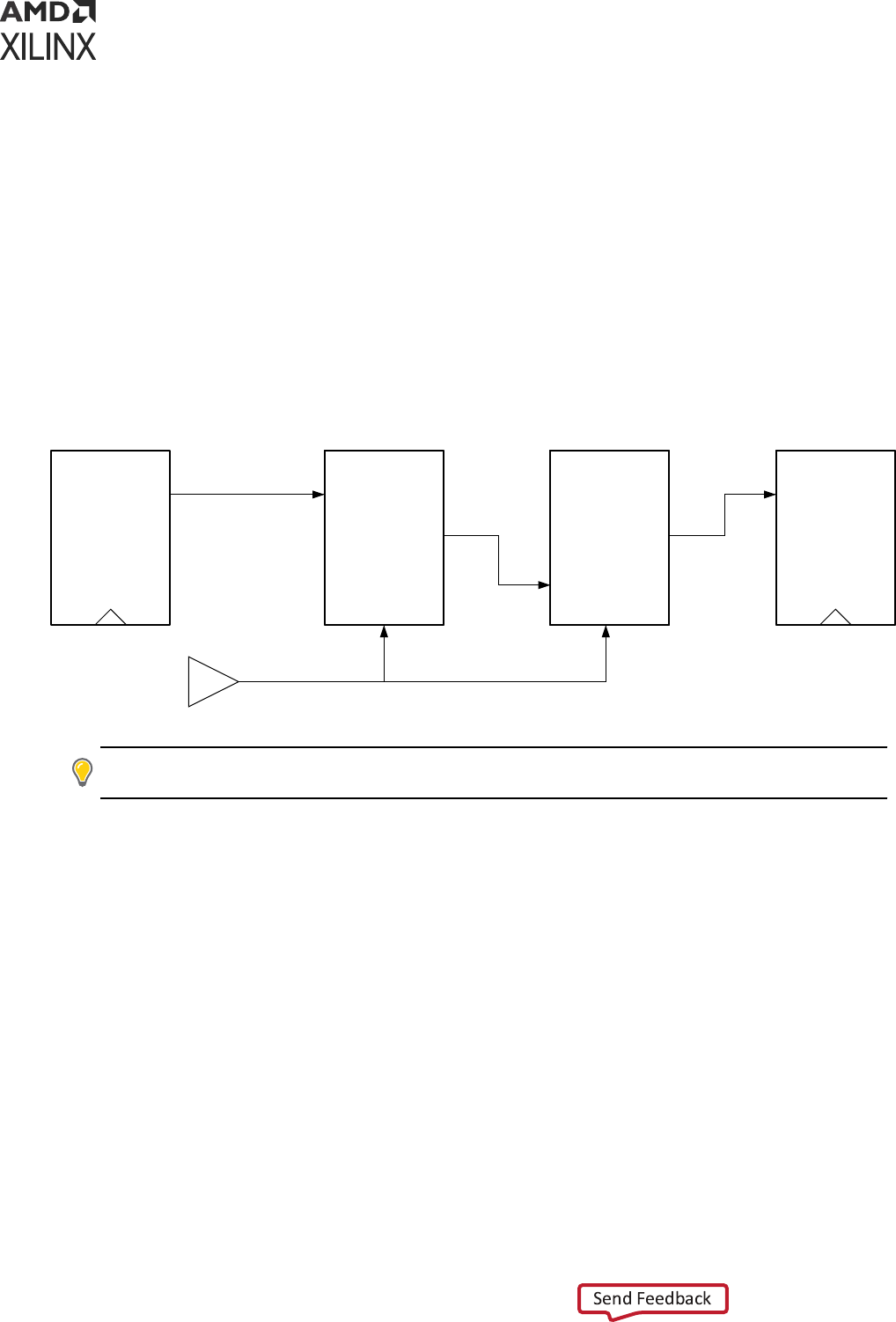
Examples of false paths include:
• Clock domain crossings in which double synchronizer logic has been added
• Registers that might be wrien once at power up
• Reset or test logic
• Ignore paths between the write and asynchronous read clocks of an asynchronous distributed
RAM (when applicable)
The following gure shows an example of a non-funconal path. Because both mulplexers are
driven by the same select signal, the path from Q to D does not exist, and should be dened as a
false path.
Figure 81: Non-Functional Path Example
REGISTER MUX
Q 0
1
MUX
0
1
REGISTER
D
X14363-120415
TIP: Use a Mulcycle constraint in place of a False Path constraint when: (1) your intent is only to relax the
ming requirements on a synchronous path; but (2) the path sll must be med, veried and opmized.
Reasons to remove false paths from the ming analysis include:
• Decrease Runme: When false paths have been removed from the ming analysis, the tool
does not need to me or opmize those non-funconal paths. Having non-funconal paths
visible to the ming and opmizaon engines can result in a large runme penalty.
• Enhance Quality of Results (QOR): Removing false paths can greatly enhance the Quality of
Results (QOR). The quality of the synthesized, placed, and opmized design is greatly
impacted by the ming issues that the tool tries to solve.
If some non-funconal paths have ming violaons, the tool might try to x those paths
instead of working on the real funconal paths. Not only might the design unnecessarily
increase in size (such as logic cloning), but the tool might skip xing real issues because non-
funconal paths have larger violaons that overshadow other real violaons. The best results
are always achieved with a realisc set of constraints.
Chapter 5: Timing Exceptions
UG903 (v2022.1) June 1, 2022 www.xilinx.com
Using Constraints 123

False paths are dened inside the tool with the Xilinx Design Constraints (XDC) command
set_false_path:
set_false_path [-setup] [-hold] [-from <node_list>] [-to <node_list>] \ [-
through <node_list>]
You can use the following addional opons to the command to ne tune the path specicaon.
For detailed informaon about all supported command line opons, see the Vivado Design Suite
Tcl Command Reference Guide (UG835).
• The list of nodes for the -from opon should be a list of valid start-points. A valid startpoint is
a clock object, a clock pin of a sequenal element, or an input (or inout) primary port. Mulple
elements can be provided.
• The list of nodes for the -to opon should be a list of valid endpoints. A valid endpoint is a
clock object, an output (or inout) primary port, or a sequenal element input data pin. Mulple
elements can be provided.
• The list of nodes for the -through opon should be a list of valid pins, ports, or nets.
Mulple elements can be provided.
CAUTION! Be careful when using
-through
opon without
-from
and
-to
because it removes from
ming analysis any path going through this list of pins or ports. Be especially careful when the ming
constraints are designed for an IP or a sub-block, but then used in a dierent context or a larger project.
Many more paths than expected could be removed when
-through
is used alone.
The order of the -through opon is important. See the following examples. For example, the
following two commands are dierent:
set_false_path -through cell1/pin1 -through cell2/pin2
set_false_path -through cell2/pin2 -through cell1/pin1
The following example removes the ming paths from the reset port to all the registers:
set_false_path -from [get_port reset] -to [all_registers]
The following example disables the ming paths between two asynchronous clock domains (for
example, from clock CLKA to clock CLKB):
set_false_path -from [get_clocks CLKA] -to [get_clocks CLKB]
The previous example disables the paths from clock CLKA to clock CLKB. Paths from clock CLKB
to clock CLKA are not disabled. Accordingly, disabling all the paths between the two clock
domains in either direcon requires two set_false_path commands:
set_false_path -from [get_clocks CLKA] -to [get_clocks CLKB]
set_false_path -from [get_clocks CLKB] -to [get_clocks CLKA]
Chapter 5: Timing Exceptions
UG903 (v2022.1) June 1, 2022 www.xilinx.com
Using Constraints 124

IMPORTANT! Although the previous two set_false_path examples perform what is intended, when two or
more clock domains are asynchronous and the paths between those clock domains should be disabled in
either direcon, Xilinx recommends using the
set_clock_groups
command instead:
set_clock_groups -group CLKA -group CLKB
In the non-funconal path example shown in Figure 81, the false path can be set using the -
through opon instead of using the -from or -to opon. See Figure 82.
Figure 82: Non-Functional Path Example
REGISTER MUX1
Q
MUX2
a0
a1
REGISTER
Da0
a1
X14364-120415
This ensures that all the paths going through the path shown above are selected without needing
to nd specic paerns for the startpoints and endpoints.
set_false_path -through [get_pins MUX1/a0] -through [get_pins MUX2/a1]
Note: The order of the -through opon is important. In the above example, the order ensures that the false
paths go through pin MUX1/a0 rst and then pin MUX2/a1.
Another common example is with asynchronous dual-ports distributed RAM. The write
operaons are synchronous to the clock RAM but the read operaons can be asynchronous
when permied by the design. In this case, it is safe to false paths the ming paths between the
write and the read clocks.
There are two ways to do this:
• Dene a false path from the write registers before the RAM to the registers aer the RAM
receiving the read clock:
set_false_path -from [get_cells <write_registers>] -to [get_cells
<read_registers>]
On the Vivado Design Suite example project WAVEGen (HDL):
set_false_path -from [get_cells -hier -filter {NAME =~
*gntv_or_sync_fifo.gl0.wr*reg[*]}] -to [get_cells -hier -filter {NAME=~
*gntv_or_sync_fifo.mem*gpr1.dout_i_reg[*]}]
Chapter 5: Timing Exceptions
UG903 (v2022.1) June 1, 2022 www.xilinx.com
Using Constraints 125
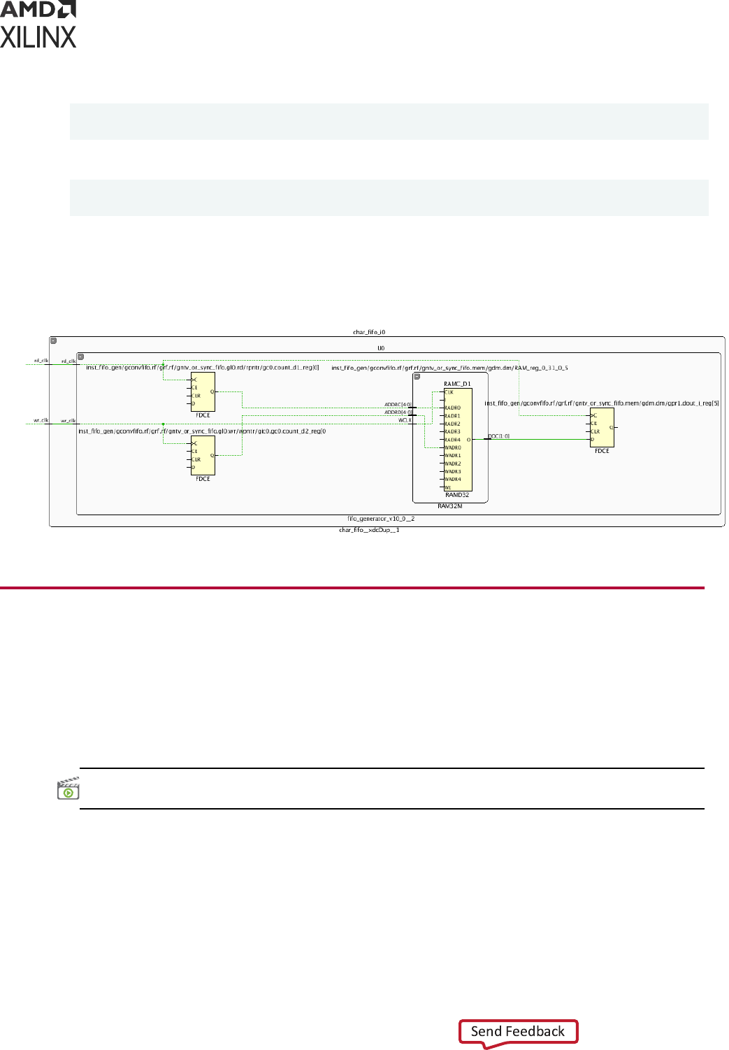
• Dene a false path starng from the pin WE of the RAM
set_false_path -from [get_cells -hier -filter {REF_NAME =~ RAM* &&
IS_SEQUENTIAL && NAME =~ <PATTERN_FOR_DISTRIBUTED_RAMS>}]
On the Vivado Design Suite example project WAVEGen (HDL):
set_false_path -from [get_cells -hier -filter {REF_NAME =~ RAM* &&
IS_SEQUENTIAL && NAME =~ *char_fifo*}]
The following gure illustrates the way the distributed RAM is driven in the WAVE (HDL)
example project.
Figure 83: Distributed RAM Driven in the WAVE Example Project
Min/Max Delays
You can override a maximum delay or a minimum delay for a path:
• Use the Maximum Delay constraint to override the default setup (or recovery) requirement on
a path.
• Use the Minimum Delay constraint to override the default hold (or removal) requirement.
VIDEO:
For training on the advanced ming excepons, including min-man delays, see the Vivado Design
Suite QuickTake Video: Advanced Timing Excepons - False Path, Min-Max Delay and Set_Case_Analysis.
Setting Maximum Delay and Minimum Delay
Constraints
The Maximum Delay constraint and the Minimum Delay constraint are set by two dierent XDC
commands. These commands accept similar opons.
Chapter 5: Timing Exceptions
UG903 (v2022.1) June 1, 2022 www.xilinx.com
Using Constraints 126

Maximum Delay Constraint Syntax
set_max_delay <delay> [-datapath_only] [-from <node_list>]
[-to <node_list>] [-through <node_list>]
Minimum Delay Constraint Syntax
set_min_delay <delay> [-from <node_list>]
[-to <node_list>] [-through <node_list>]
Addional command opons are available to ne tune the path specicaon. For more
informaon about the supported command line opons, see the Vivado Design Suite Tcl Command
Reference Guide (UG835).
List of Nodes for the -from Option
• The list of nodes for the -from opon should preferably be a list of valid startpoints. A valid
startpoint is a clock, an input (or inout) port, or the clock pin of a sequenal element, such as a
register or a RAM. Using a node that is not a valid startpoint results in path segmentaon. The
path segmentaon is covered in the next secon.
• Mulple elements can be provided.
List of Nodes for the -to Option
• The list of nodes for the -to opon should preferably be a list of valid endpoints. A valid
endpoint is a clock, an output (or inout) port or the data pin of a sequenal cell.
• Using a node that is not a valid endpoint results in path segmentaon. For more informaon,
see Path Segmentaon.
• Mulple elements can be provided.
List of Nodes for the -through Option
• The list of nodes for the -through opon should be a list of valid pins, ports, or nets.
• Mulple elements can be provided.
By default, the ming engine includes the clock skew inside the slack computaon.
The -datapath_only opon can be used to remove the clock skew from the slack
computaon. The -datapath_only opon is supported only by the set_max_delay
command, and requires the -from opon.
The following table summarizes the impact of -datapath_only in the behavior of
set_max_delay constraint.
The common behavior for the path delay calculaon of set_max_delay with or without -
datapath_only is:
Chapter 5: Timing Exceptions
UG903 (v2022.1) June 1, 2022 www.xilinx.com
Using Constraints 127
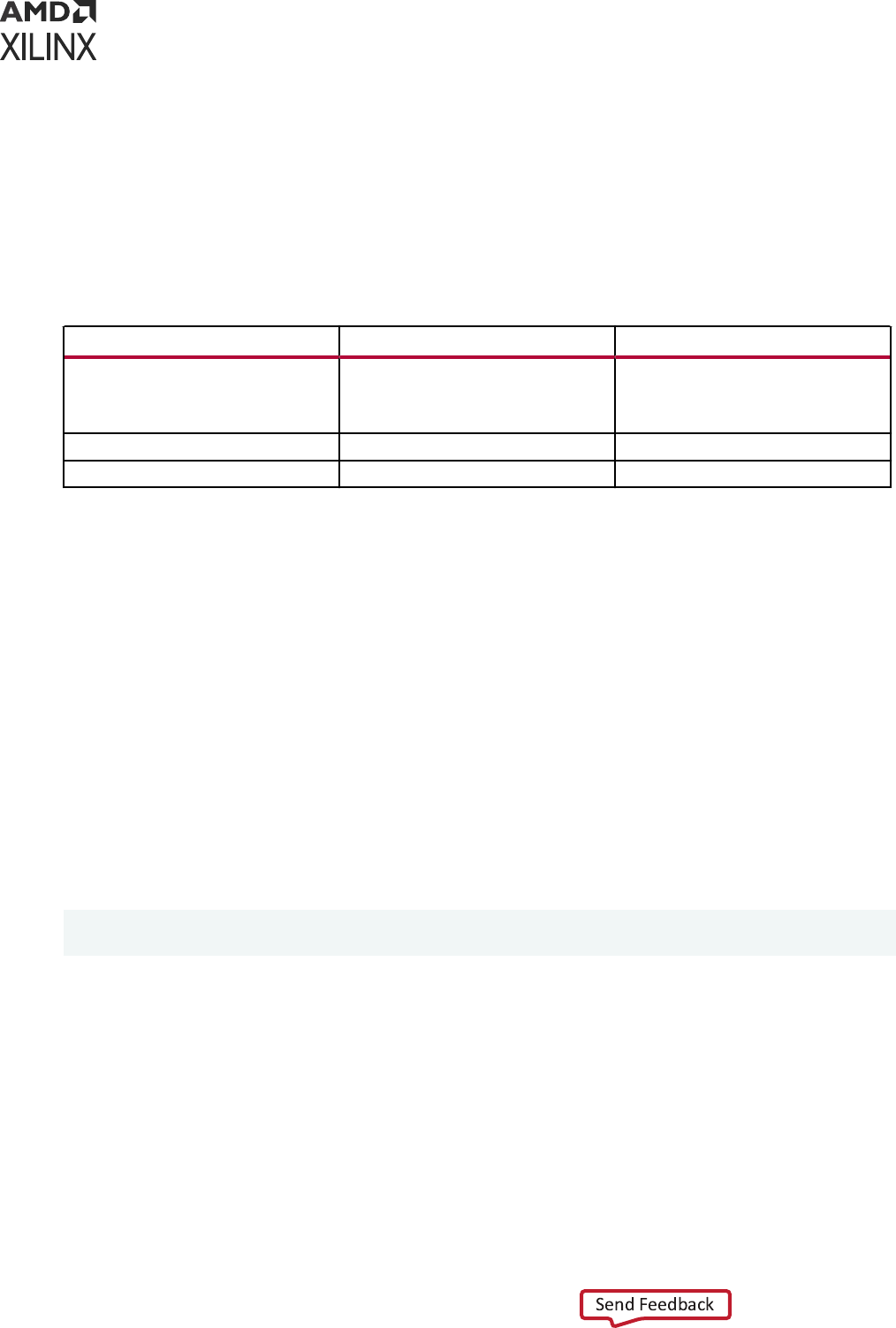
• Input delay is included in the path delay calculaon when the path starts on an input port and
that a set_input_delay has been specied on the port
• Output delay is included in the path delay calculaon when the path ends on an output port
and that a set_output_delay has been specied on the port
• The data pin setup me is included in the path delay calculaon when the path ends on the
data pin of a sequenal element.
Table 9: Differences Between Max Delay Constraint With and Without -datapath_only
set_max_delay set_max_delay -datapath_only
Path delay calculation Skew included when the constraint
starts on the clock pin of a sequential
element or ends on the data pin of a
sequential element.
Skew never included.
Hold Requirement Untouched False-ed path
-from Option Optional Mandatory
Consequences of Setting Maximum Delay or Minimum Delay
Constraints on a Path
When -datapath_only opon is not used, seng a Maximum Delay constraint on a path,
does not modify the minimum requirement on that path. The hold (or removal) check on that
path remains the default one.
Note: Using the -datapath_only opon with set_max_delay results in the hold requirement being
ignored on that/those path(s) (some internal set_false_path -hold constraints are generated).
Similarly, seng a Minimum Delay constraint on a path does not modify the default setup (or
recovery) check.
If a path has only, for example, a max delay requirement, the path can be constrained with a
combinaon of set_max_delay and set_false_path commands. See the following
example:
set_max_delay 5 -from [get_pins FD1/C] -to [get_pins FD2/D] set_false_path -
hold -from [get_pins FD1/C] -to [get_pins FD2/D]
The above example sets a 5 ns setup requirement for the path starng on FD1/C and ending on
FD2/D. There is no minimum requirement due to the set_false_path command.
Constraining Input or Output Logic
The set_max_delay command and the set_min_delay command are not typically used to
constrain the input or output logic. The input logic between the input ports and the rst level of
registers is typically constrained with the set_input_delay command. This command
provides the opon to associate a clock with the input ports.
Chapter 5: Timing Exceptions
UG903 (v2022.1) June 1, 2022 www.xilinx.com
Using Constraints 128

For the same reason, the output logic between the last level of registers and the output ports is
typically constrained with the set_output_delay command. However, the set_max_delay
command and the set_min_delay command are typically used to constrain pure
combinaonal path between primary input ports and primary output port (in-to-out I/O paths).
Constraining Asynchronous Signals
The set_max_delay command can also be used to constrain asynchronous signals that do not
have a clock relaonship, but which require maximum delay.
For example, ming paths between two asynchronous clock domains can be disabled with the
set_clock_groups command (recommended) or the set_false_path command (not
recommended). This assumes that you have properly designed the inter-clock domains with, for
instance, a double registers synchronizer or a FIFO. However, you must sll ensure that the path
delay between the two clock domains is not unnecessarily high.
In some mul-bit CDC scenarios the skew between the bits must be within certain requirements.
Even though the skew can be constrained through the Bus Skew constraint (set_bus_skew), it
must be ensured that the path delay between the two clock domains is not unnecessarily high.
This can be done by replacing the set_false_path or set_clock_groups constraints inside
the source XDC le on the relevant path(s) with set_max_delay –datapath_only. Refer to
Chapter 6: CDC Constraints for further informaon on constraining CDC paths.
Note: There is runme impact between a False Path constraint and a Max Delay constraint because the
paths are med with Max Delay.
If a maximum delay must be specied for some or for all the paths between two clock domains,
then you must use the command set_max_delay -datapath_only to constrain those
paths. In this case, set_clock_groups cannot be used to dene the two clock domains as
asynchronous, as it supersedes the set_max_delay constraint in terms of constraint priority.
Other cross clock domains paths must then be constrained with a combinaon of
set_false_path or set_max_delay constraints.
See the following example:
set_max_delay <delay> -datapath_only -from
<startpoints_source_clock_domain> \
-to <endpoints_destination_clock_domain>
Path Segmentation
Unlike other XDC constraints, the set_max_delay command and the set_min_delay
command can accept, in the case of -from and -to opons, a list of invalid startpoints or
endpoints respecvely.
When an invalid startpoint is specied, the ming engine stops the propagaon of the ming
going through the node so that the node becomes a valid startpoint.
Chapter 5: Timing Exceptions
UG903 (v2022.1) June 1, 2022 www.xilinx.com
Using Constraints 129
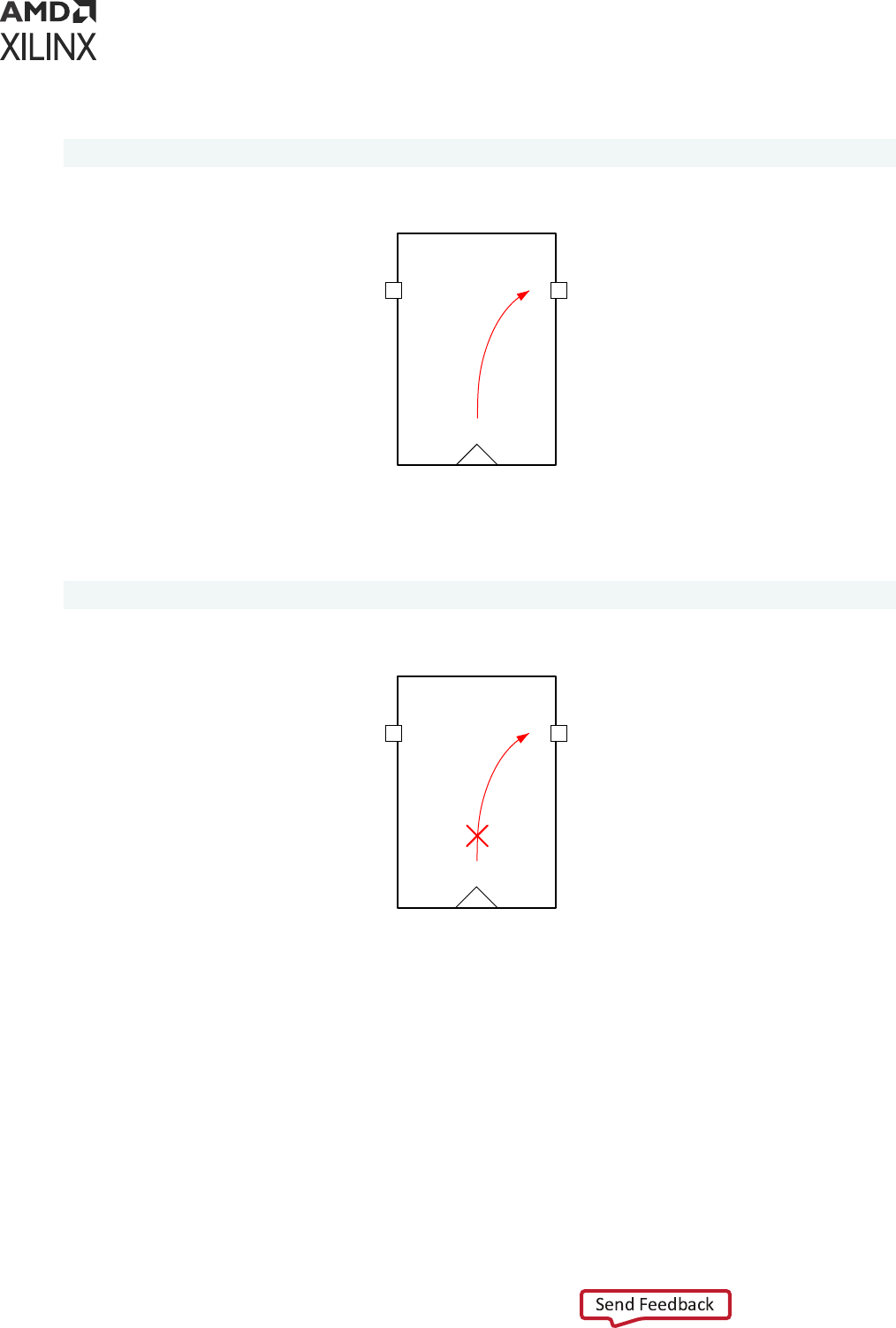
In the following example, the only valid startpoint is FD1/C:
set_max_delay 5 -from [get_pins FD1/C]
Figure 84: Original Timing Arc
FD1
QD
C
X14365-120415
If the constraint is applied to FD1/Q, the ming engine stops the propagaon through the arc C-
>Q to make the pin Q a valid startpoint:
set_max_delay 5 -from [get_pins FD1/Q]
Figure 85: Timing Not Propagating after Path Segmentation
FD1
QD
C
X14366-120415
The process of stopping the propagaon of the ming to create a valid startpoint is called path
segmentaon. Path segmentaon aects both max and min delay analysis. Path segmentaon
also aects any ming constraint going through those nodes (FD1/C and FD1/Q).
Note: Because of Path Segmentaon, no clock inseron delay is used for the launch clock for paths starng
from FD1/Q. This can potenally result in large skew because the clock skew of the endpoints is sll taken
into account. See the following gure.
Chapter 5: Timing Exceptions
UG903 (v2022.1) June 1, 2022 www.xilinx.com
Using Constraints 130
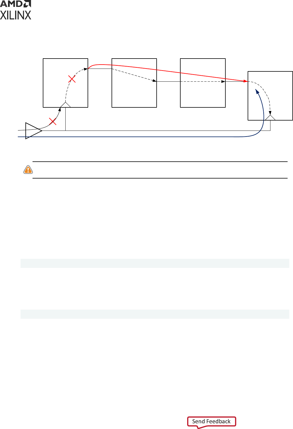
Figure 86: Path Segmentation Result in Large Skew
Q
FD1
D IO
I1
I2
O
LUTA
IO
I1
I2
O
LUTB
Q
FD2
D
clock insertion delay
BUFG
X14367-120415
CAUTION! Path segmentaon can have unexpected consequences. Avoid path segmentaon altogether,
or use it very carefully.
Aer path segmentaon, there is no default hold requirement on the path. Assuming the -
datapath_only opon has not been specied, use the set_min_delay command to set a
hold requirement on the path if necessary.
Because of the risks, a crical warning is issued when a path segmentaon occurs.
If you targeted the output FD1/Q as the startpoint in order to avoid taking the clock skew into
account, Xilinx recommends using the -datapath_only opon. Instead, see the following
example:
set_max_delay 5 -from [get_pins FD1/C] -datapath_only
In the same way, when an invalid endpoint is specied, the ming engine stops the propagaon
aer the node so that the node becomes a valid endpoint.
In the following example, the max delay is specied on LUTA/O, which is not a valid endpoint:
set_max_delay 5 -from [get_pins LUTA/O]
This is shown in the following gure.
Chapter 5: Timing Exceptions
UG903 (v2022.1) June 1, 2022 www.xilinx.com
Using Constraints 131
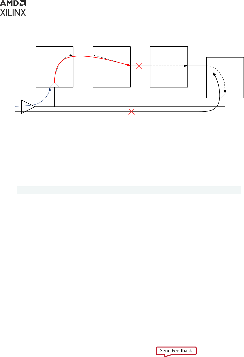
Figure 87: Path Segmentation When an Invalid Endpoint is Specified
Q
REGA
D IO
I1
I2
O
LUTA
IO
I1
I2
O
LUTB
Q
REGB
D
BUFG
X14368-120415
To make LUTA/O a valid endpoint, the ming stops propagang aer LUTA/O. As a result, all
ming paths going through LUTA/O are impacted for both setup and hold. For the path starng
on REGA/C and ending on LUTA/O, only the inseron delay of the launch clock is taken into
account. This can result in very large skew.
Because path segmentaon stops the propagaon through the ming arcs, it can have
unexpected consequences. All the ming paths going through those nodes are impacted.
In the following example, a max delay has been set between LUTA/O and REGB/D:
set_max_delay 6 -from [get_pins LUTA/O] -to [get_pins REGB/D]
This is shown in the following gure.
Chapter 5: Timing Exceptions
UG903 (v2022.1) June 1, 2022 www.xilinx.com
Using Constraints 132
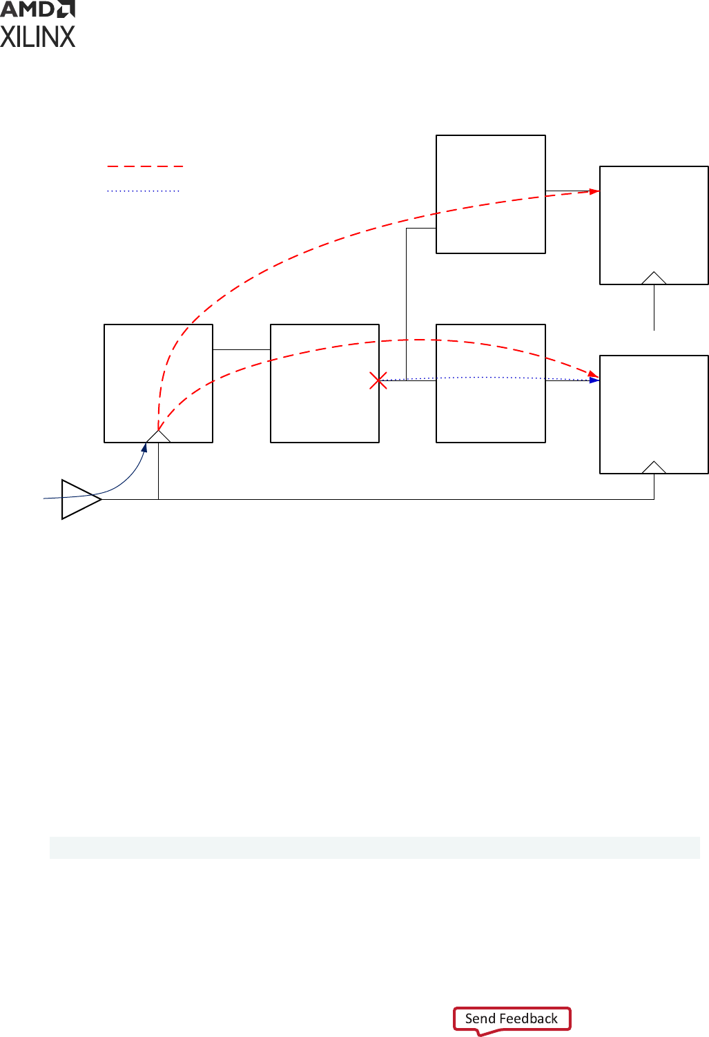
Figure 88: Path Segmentation Breaking Multiple Paths
Q
REGA
D IO
I1
I2
O
LUTA
IO
I1
I2
O
LUTB
Q
REGB
D
BUFG
IO
I1
I2
O
LUTC
Q
REGC
D
Broken Paths
Constrained Paths
Segmentation
X14369-120415
Because the pin LUTA/O is not a valid startpoint, a path segmentaon occurs and the ming arcs
from LUTA/I* and LUTA/O are broken. Even though the set_max_delay constraint was set
between LUTA/O and REGB/D only, other paths such as the path between REGA/C and
REGC/D are also broken.
Path Segmentation and Timing Exception
Path segmentaon can result in the percepon that the priority between the ming excepons is
altered, which is actually not the case.
There can be a dierence on whether a set_max_delay constraint is superseded by a
set_clock_groups constraint. Consider the following two scenarios.
Scenario 1
set_max_delay <ns> -datapath_only -from <instance> -to <instance>
In this scenario, instance names are provided for -from/-to. The set_max_delay constraint is
always overridden by set_clock_groups -asynchronous, because Vivado always selects
valid startpoints when an instance is provided.
Chapter 5: Timing Exceptions
UG903 (v2022.1) June 1, 2022 www.xilinx.com
Using Constraints 133

Scenario 2
set_max_delay <ns> -datapath_only -from <pin> -to <pin | instance>
In this scenario, if the pin name provided with -from results in path segmentaon, then that
parcular set_max_delay constraint is not overriden by set_clock_groups -
asynchronous. The reason behind is that the path segmentaon forces the path starng on the
pin name to no longer being considered launched by the rst clock domain. As a result, this path
is no longer covered by the set_clock_groups constraints and the set_max_delay
constraint get applied.
Case Analysis
In some designs, certain signals have a constant value in specic modes. For instance, in
funconal modes, the test signals do not toggle and are therefore ed either to VDD or VSS
depending on their acve level. This also applies to signals that do not toggle aer the design has
been powered up. In the same way, today's designs have mulple funconal modes and some
signals that are acve in some of the funconal modes might be inacve in other modes.
To help reduce the analysis space, runme and memory consumpon, it is important to let the
Stac Timing Engine know about the signals that have a constant value. This is also crical to
ensure that non-funconal paths and irrelevant paths are not reported.
A signal is declared as inacve to the ming engine with the set_case_analysis command.
The command applies to pins and/or ports.
Note: Aer a case analysis is set on a pin, the ming arcs related to that pin are disabled. The ming engine
does not report any path going through disabled ming arcs.
VIDEO:
For training on the advanced ming excepons, including
set_case_analysis
, see the
Vivado Design Suite QuickTake Video: Advanced Timing Excepons - False Path, Min-Max Delay and
Set_Case_Analysis.
The syntax of the set_case_analysis command is:
set_case_analysis <value> <pins or ports objects>
The parameter <value> can be any of the following:
0, 1, zero, one, rise, rising, fall, or falling
When the values rise, rising, fall, or falling are specied, this means that the given pins or ports
should only be considered for ming analysis with the specied transion. The other transion is
disabled.
A case value can be set on a port, a pin of a leaf cell, or a pin of a hierarchical module.
Chapter 5: Timing Exceptions
UG903 (v2022.1) June 1, 2022 www.xilinx.com
Using Constraints 134
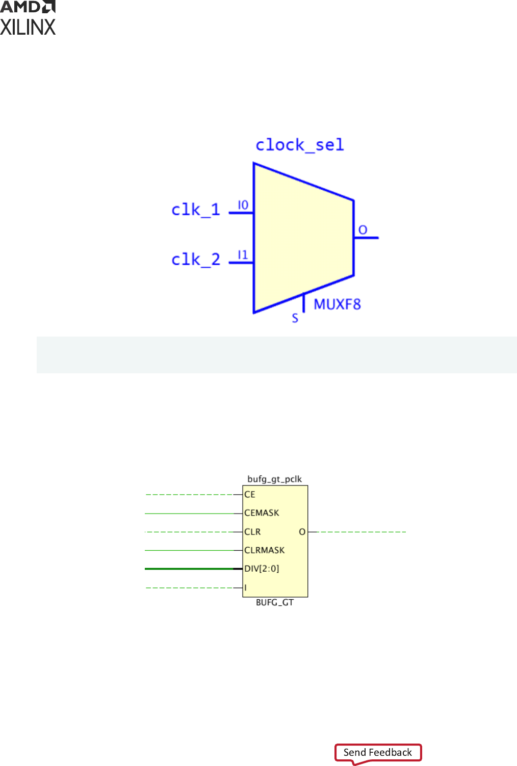
In the example below, two clocks are created on the input pins of the mulplexer clock_sel
but only clk_2 is propagated through the output pin aer seng the constant value on the
selecon pin S.
Figure 89: Clock Example
create_clock -name clk_1 -period 10.0 [get_pins clock_sel/I0]
create_clock -name clk_2 -period 15.0 [get_pins clock_sel/I1]
set_case_analysis 1 [get_pins clock_sel/S]
In the example below, the BUFG_GT has a dynamic clock division as its DIV[2:0] pins driven by
some logic instead of being ed to VCC/GND.
Figure 90: BUFG_GT/DIV Example
Chapter 5: Timing Exceptions
UG903 (v2022.1) June 1, 2022 www.xilinx.com
Using Constraints 135

In such case, the tool assumes the worst possible scenario for the output clock (divide by 1) and
propagates the incoming clock to the buer output. This worst-case scenario might be
pessimisc and over-constrain the design if a clock division of 1 is never exercised. It is possible
to control the auto-generated clock on the BUFG_GT output pin by seng the DIV[2:0] bus
with a set_case_analysis constraint.
For example, if the worst-case clock divider is by 3, then the following case analysis should be
applied to the BUFG_GT:
set_case_analysis 0 [get_pins bufg_gt_pclk/DIV[0] ]
set_case_analysis 1 [get_pins bufg_gt_pclk/DIV[1] ]
set_case_analysis 0 [get_pins bufg_gt_pclk/DIV[2] ]
Note: For UltraScale™ and UltraScale+™ devices, the GT_CHANNEL has mulple input clocks that
propagate to the output of the GT_CHANNEL (such as TXOUTCLK) through mulple levels of internal
muxes. The case analysis can be used in a similar way on the GT_CHANNEL clock muxing control signals
(such as TXSYSCLKSEL, TXOUTCLKSEL) to select which of the input or internal clocks should be
propagated to the output of the GT_CHANNEL.
Disabling Timing Arcs
You can disable ming arcs inside the cell with the set_disable_timing command. Only
ming arcs going from input to output ports of a cell can be disabled.
Note: The set_disable_timing command can also be used to disable a ming arc from a port or a wire.
In such cases, the command line opons -from and -to are not used and only the port object(s) or ming
arc object(s) are specied.
Some ming arcs are automacally disabled by the mer to handle specic cases. For instance,
combinaonal feedback loops are not recommended and cannot be properly med. The mer
breaks such loops by disabling one of the ming arcs inside the loop.
Another example is a case analysis set on a MUX. By default, all the data inputs of a MUX are
propagated to the output port but when a case analysis is set on the select signals, only one data
input port gets propagated to the output port. This is done by the mer by breaking ming arcs
from the other data input ports to the output port.
The set_disable_timing command gives you the ability to manually break cell ming arcs in
the design. You can, for example, decide which ming arc(s) of a combinaonal feedback loop
should be disabled to break the loop instead of leng the tool make this determinaon.
Also, suppose that mulple clocks arrive on a LUT input pins but only one clock should be
propagated to the LUT output port. This scenario can be handled by breaking the ming arcs
associated to the clocks that should not propagate.
Chapter 5: Timing Exceptions
UG903 (v2022.1) June 1, 2022 www.xilinx.com
Using Constraints 136

There is also a scenario involving LUTRAM that can be quite frequent. Inside the LUTRAM, there
is physical path from WCLK pin to the output O pin between the write and read clocks. However,
LUTRAM-base asynchronous FIFO are designed in such way that this CDC path WCLK->O
cannot happen by construcon. Nevertheless, this ming arc is enabled and can result is the
mer reporng paths through this WCLK->O ming arc. This arc can also trigger some
TIMING-10 DRC violaons. In such case, the user should disable the WCLK->O arc so that those
paths are not med and reported and that they do not trigger invalid DRC violaons. This ming
arc is automacally disabled in the current implementaon of the Xilinx LUTRAM-based FIFO.
Note: Aer a ming arc is disabled, no ming path will be reported by the mer through this arc. You
should be very careful to not disable any valid ming arc. This might result is masking some ming
violaons and/or ming problems that could result in the design failing in hardware.
The syntax for the set_disable_arc command is:
set_disable_timing [-from <arg>] [-to <arg>] [-quiet] [-verbose] <objects>
Only pin names and not Vivado tools objects can be provided to the -from and -to command
line opons. The pin names should also match pin names from the library cell, not design pin
names. For example:
set_disable_timing -from WCLK -to O [get_cells inst_fifo_gen/ gdm.dm/
gpr1.dout_i_reg[*]]
The above command disables the WCLK->O ming arcs for all the LUTRAM-based asynchronous
FIFOs inst_fifo_gen/ gdm.dm/gpr1.dout_i_reg[*].
The command line opons -from and -to are oponal. If -from is not specied, then all the
ming arcs ending on the pin specied with -to are being disabled. In the same way if -to is not
specied, then all the ming arcs starng on the pin specied with -from are being disabled. If
neither -from nor -to are specied, then all the ming arcs of the cells specied in the
command are disabled.
You can use the command report_disable_timing to list all the ming arcs that have been
automacally disabled by the mer as well as manually disabled by the user. Be careful as the list
can be very large. Use the -file command line opon to save the result in a le.
Note: report_disable_timing can be scoped to one or more hierarchical module(s) with -cells.
Chapter 5: Timing Exceptions
UG903 (v2022.1) June 1, 2022 www.xilinx.com
Using Constraints 137

Chapter 6
CDC Constraints
About CDC Constraints
Clock Domain Crossing (CDC) constraints apply to ming paths that have a dierent launch and
capture clock. There are synchronous CDC and asynchronous CDC depending on the launch and
capture clocks relaonship and on the ming excepons set on the CDC paths. For example,
CDC paths between synchronous clocks but covered by false path constraints are not med, and
consequently are treated as asynchronous CDCs.
Asynchronous CDC paths can be safe or unsafe. The terminology of safe and unsafe for
asynchronous CDC paths is dierent from the terminology used for inter-clock ming analysis
(see report_clock_interacon). An asynchronous CDC path is considered safe when it uses a
synchronizaon circuitry to prevent metastability of the capture sequenal cell.
For more informaon, refer to this link in the Vivado Design Suite User Guide: Design Analysis and
Closure Techniques (UG906).
The ming analysis of CDC paths can be fully ignored by using set_false_path or
set_clock_groups constraints, or parally analyzed by using set_max_delay -
datapath_only. In addion, the mulbit CDC paths capture me spread can be constrained
using the set_bus_skew constraint.
Constraining Bus Skew
About Bus Skew Constraints
The bus skew constraint is used to set a maximum skew requirement between several
asynchronous CDC paths. The bus skew is not the tradional clock skew associated with a ming
path. Instead, it corresponds to the largest capture me dierence across all the paths that are
covered by a same set_bus_skew constraint. The bus skew requirement applies to both Fast
and Slow corners, but it is not analyzed across the corners.
Chapter 6: CDC Constraints
UG903 (v2022.1) June 1, 2022 www.xilinx.com
Using Constraints 138

The intent of the bus skew constraint is to limit the number of source clock edges that can launch
a data and be captured by a single desnaon clock edge. The tolerance depends on the CDC
synchronizaon scheme used for the constrained paths. The bus skew constraint is typically used
for the following CDC topologies:
• Gray-coded bus transfer, such as in asynchronous FIFOs
• Mul-bit CDC implemented with CE, MUX, or MUX Hold circuitry
• Conguraon registers
Although the set_bus_skew command does not prevent a bus skew constraint to be set on a
safely med synchronous CDC, such a constraint is not needed. The setup and hold checks
already ensure a safe transfer between two safely med synchronous CDC paths.
The CDC scenarios for bus skew constraints are:
• Asynchronous CDC covered with set_clock_groups
• Asynchronous CDC enrely covered with set_false_path and/or set_max_delay -
datapath_only
• Synchronous CDC paths covered with set_false_path and/or set_max_delay -
datapath_only
The bus skew constraint is not a ming excepon; rather, it is a ming asseron. Therefore, it
does not interfere with the ming excepons (set_clock_group, set_false_path,
set_max_delay, set_max_delay -datapath_only, and set_multicycle_path) and
their precedence.
The bus skew constraint is only opmized by the route_design command. To report the
set_bus_skew constraints, use the report_bus_skew command from the command line or
Reports → Timing → Report Bus Skew from the GUI. The bus skew constraints are not reported
inside the Timing Summary report (report_ming_summary).
Syntax of the set_bus_skew Command
The syntax of the set_bus_skew command with the basic opons is:
set_bus_skew [-from <args>] [-to <args>] [-through <args>] <value>
The list of objects for the -from opon should be a list of valid startpoints. A valid startpoint for
set_bus_skew is a clock, or the clock pin of a sequenal element, such as a register or a RAM.
An input (or inout) port is not supported by set_bus_skew.
The list of nodes for the -to opon should be a list of valid endpoints. A valid endpoint for
set_bus_skew is a clock, or the data pin of a sequenal cell. An output (or inout) port is not
supported by set_bus_skew.
Chapter 6: CDC Constraints
UG903 (v2022.1) June 1, 2022 www.xilinx.com
Using Constraints 139
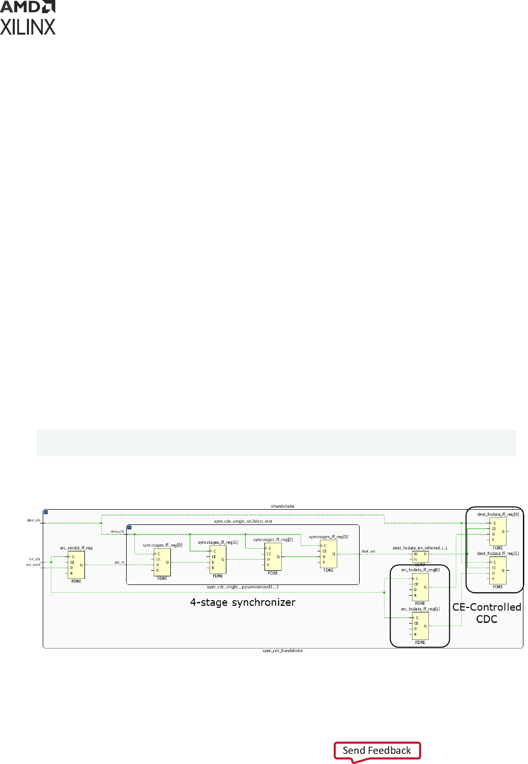
The list of nodes for the -through opon should be a list of valid pins, or nets.
Although the -from and -to command line opons can refer to clocks, Xilinx recommends that
you be more specic and specify a limited list of startpoints and endpoints per constraint. This
will ensure that not too many paths get covered by each constraint and that each constraint can
be reasonably met.
Note: Both the -from and -to opons must be specied when specifying a bus skew constraint.
Note: Xilinx recommends seng a bus skew constraint on paths with no fanout. Also, each bus skew
constraint must cover at least two startpoints and two endpoints.
The bus skew value must be realisc and reasonable. Xilinx recommends to use a value larger
than half the minimum period of the source and desnaon clocks. The recommended value for
the bus skew also depends on the CDC topology as illustrated by the following examples.
set_bus_skew Example One
In this example, the CDC is part of a handshake mechanism. The source clock domain generates a
send signal when data is available to be sampled. The desnaon clock domain uses a 4-stage
synchronizer for the send signal. Aer the 4-stage synchronizer, the signal drives the Clock
Enable pin of the CDC desnaon registers. In such Clock-Enabled Control CDC structure, the
bus skew must be adjusted to the number of stages on the CE path since it represents the
number of desnaon clock cycles for which the data is valid.
If the source clock period is 5 ns and the desnaon clock period is 2.5 ns, the bus skew on the
CDC path should be set to 10 ns (4×2.5 ns).
set_bus_skew -from [get_cells src_hsdata_ff_reg*] -to [get_cells
dest_hsdata_ff_reg*] 10.000
Figure 91: set_bus_skew Example One
X18887-031717
Chapter 6: CDC Constraints
UG903 (v2022.1) June 1, 2022 www.xilinx.com
Using Constraints 140
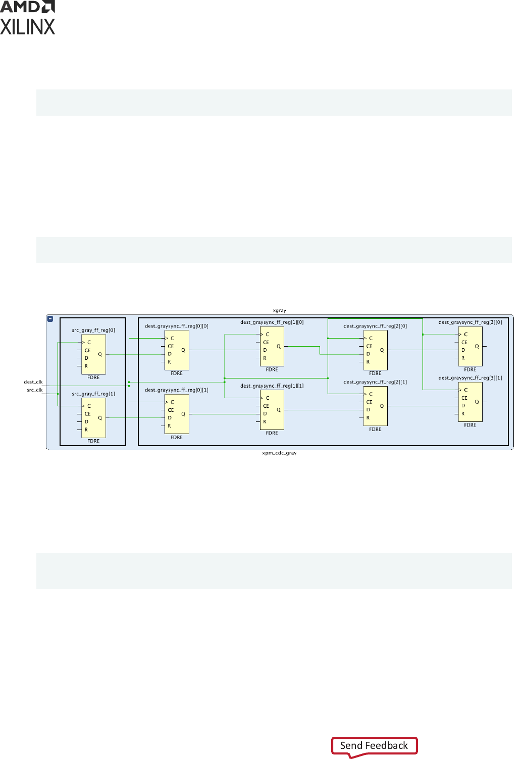
Note: For completeness, the CDC needs an addional set_max_delay constraint to ensure that the
source and desnaon registers are not placed too far apart:
set_max_delay -datapath_only -from [get_cells src_hsdata_ff_reg*] -to
[get_cells dest_hsdata_ff_reg*] 10.000
set_bus_skew Example Two
In this example, the CDC is on a gray-coded bus. The system must ensure that only one
transion of the gray-coded bus is captured by the desnaon clock domain at the same me.
If the source clock period is 5 ns and the desnaon clock period is 2.5 ns, the bus skew on the
CDC path should be set to 2.5 ns (desnaon clock period).
set_bus_skew -from [get_cells src_gray_ff_reg*] -to [get_cells
{dest_graysync_ff_reg[0]*}] 2.500
Figure 92: set_bus_skew Example Two
X18854-031717
Note: For completeness, the CDC needs an addional set_max_delay constraint to ensure that the
source and desnaon registers are not placed too far apart. In this case, the max delay is set to the source
clock period as the CDC is between a slower clock to a faster clock and only one transion of the bus
should be captured by the desnaon clock domain:
set_max_delay -datapath_only -from [get_cells src_gray_ff_reg*] -to
[get_cells
{dest_graysync_ff_reg[0]*}] 5.000
Set Bus Skew Dialog Box
In the Vivado
®
IDE, you can set bus skew constraints in mulple ways:
• Through the Timing Constraints Editor. Select Window → Timing Constraint → Asseron →
Set Bus Skew.
Chapter 6: CDC Constraints
UG903 (v2022.1) June 1, 2022 www.xilinx.com
Using Constraints 141
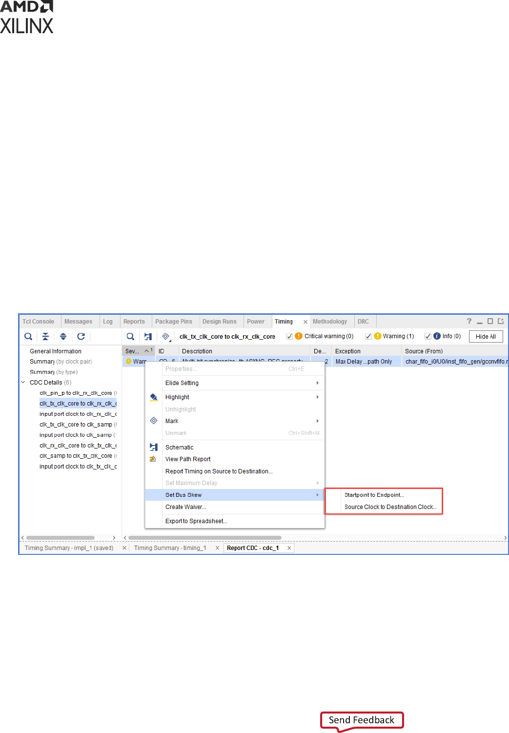
From the Timing Constraints Editor, you can add, remove, or modify bus skew constraints.
Note: Locked IP bus skew constraints cannot be edited.
• Through the Report CDC GUI. Select Reports → Timing → Report CDC.
Inside the CDC Details tables, you must select one or more rows to include at least two or more
startpoints and two or more endpoints. When you right-click and select Set Bus Skew, there are
two opons:
• Startpoint to Endpoint: Set a bus skew constraint between the startpoints and endpoints
included in the selected row(s).
• Source Clock to Desnaon Clock: Set bus skew constraints between the clock domains of
the startpoints and endpoints.
Note: It is typically not recommended to set a bus skew constraints between clock domains, because it
will apply to more paths than needed. This will result in longer implementaon runme and impossible
ming closure.
Figure 93: Setting Bus Skew within Report CDC
Note: Vivado does not verify the validity of seng a bus skew constraint on the selected objects. You must
ensure that a bus skew constraint makes sense with the selected objects.
In the Set Bus Skew dialog box, you can set the bus skew value, the startpoints, and endpoints, as
shown in the following gure.
Chapter 6: CDC Constraints
UG903 (v2022.1) June 1, 2022 www.xilinx.com
Using Constraints 142
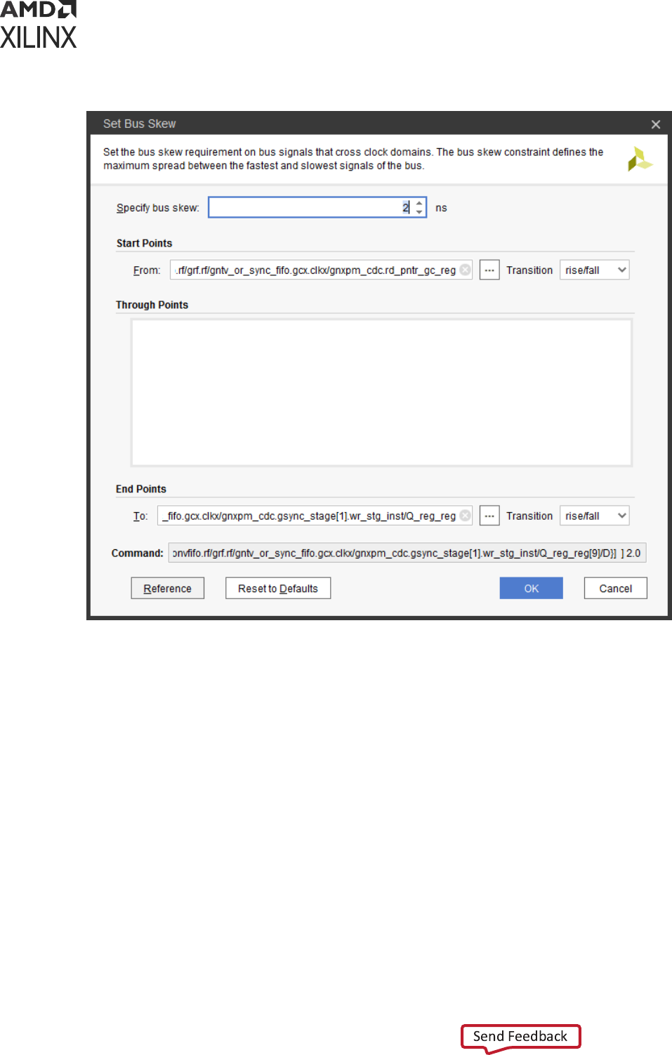

Chapter 7
XDC Precedence
About XDC Precedence
The precedence rules for Xilinx
®
Design Constraints (XDC) are inherited from Synopsys Design
Constraints (SDC). This chapter discusses how constraint conicts or overlaps are resolved.
XDC Constraints Order
XDC constraints are commands interpreted sequenally. For equivalent constraints, the last
constraint takes precedence.
Constraints Order Example:
> create_clock -name clk1 -period 10 [get_ports clk_in1]
> create_clock -name clk2 -period 11 [get_ports clk_in1]
In this example, the second clock denion overrides the rst clock denion because:
• They are both aached to the same input port.
• The create_clock -add opon was not used.
Exceptions Priority
If constraints overlap (for example, if several ming excepons are applied to the same path), the
priority from highest to lowest is:
1. Clock Groups (set_clock_groups)
2. False Path (set_false_path)
3. Maximum Delay Path (set_max_delay) and Minimum Delay Path (set_min_delay)
4. Mulcycle Paths (set_multicycle_path)
Chapter 7: XDC Precedence
UG903 (v2022.1) June 1, 2022 www.xilinx.com
Using Constraints 144

Note: The set_bus_skew constraint does not aect the above constraints precedence. The
set_bus_skew constraint does not override and is not overridden by clock groups, max delays, false
paths, and mulcycle paths. The reason is that the bus skew is not a constraint on a parcular path, but a
constraint between paths.
Note: The priority between the False Path, Maximun/Minimum Delay and Mulcycle Path can be altered
using the opon -reset_path. The Clock Group constraint cannot be overriden. A Maximum/Minimum
Delay or Mulcycle Path constraint can only override a previously dened False Path or Maximum/
Minimum Delay constraint when both constraints are dened with the exact same arguments for -from/-
to/-through and the latest constraint uses -reset_path.
In addion, for the same type of excepon, the more specic the constraint, the higher the
precedence. Depending on the ltering opons and the type of objects used in the constraint,
you can modify the specicity of a constraint.
The priority rule for the objects is:
1. Ports, pins, and cells
Pins of a cell are used instead of the cell itself.
2. Clocks
Clocks always have lower priority than ports, pins, and cells. A ming excepon that uses
clock object(s) always has a lower priority than another ming excepon dened with ports,
pins, and cells.
The precedence rule for the lters, from highest to lowest, is:
1. -from -through -to
2. -from -to
3. -from -through
4. -from
5. -through -to
6. -to
7. -through
IMPORTANT!
Note that cells used in either the -from or -to, always have a higher precedence than a
clock even if the clock is used in a more specic case of -from -through -to.
Exceptions Priority Example
> set_max_delay 12 -from [get_clocks clk1] -to [get_clocks clk2]
> set_max_delay 15 -from [get_clocks clk1]
In this example, the rst constraint overrides the second constraint for the paths from clk1 to
clk2.
Chapter 7: XDC Precedence
UG903 (v2022.1) June 1, 2022 www.xilinx.com
Using Constraints 145

The number of -through opons used in an excepon does not aect the precedence. The
ming engine uses the ghtest constraint.
> set_max_delay 12 -from [get_cells inst0] -to [get_cells inst1]
> set_max_delay 15 -from [get_clocks clk1] -through [get_pins hier0/p0] -
to [get_cells inst1]
In this example, the rst constraint only uses cell objects and the second constraint uses a clock
object. Although inst0 is clocked by clk1, the rst constraint overrides the second constraint
for the paths from cell inst0 to cell inst1.
Exceptions Priority with Multiple -through Options
Example
> set_max_delay 4 -through [get_pins inst0/I0]
> set_max_delay 5 -through [get_pins inst0/I0] -through [get_pins inst1/I3]
Both excepons are kept by the ming engine. The more challenging constraint is used for ming
analysis. In this example, the 4 ns max delay constraint will be used even for paths going through
the pin inst1/I3.
Exceptions Priority with -reset_path Example
> set_false_path -from [get_clocks clkA] -to [get_clocks clkB]
> set_max_delay 1 -from [get_clocks clkA] -to [get_clocks clkB] -
reset_path
The paths between clocks clkA and clkB are covered by the Max Delay with a path
requirement of 1ns. The Max Delay is dened with the same arguments for -from/-to and
species -reset_path, which overrides the False Path.
> set_false_path -from [get_clocks clkA] -to [get_clocks clkB]
> set_max_delay 1 -from [get_pins reg0/CLK] -to [get_pins reg1/D] -
reset_path
The paths between reg0/CLK and reg1/D are covered by the False Path since that constraint
has a higher precedence over the Max Delay. The Max Delay doesn't override the False Path
despite the -reset_path as it is not dened with the same arguments for -from/-to.
RECOMMENDED:
You must avoid using several ming excepons on the same paths, so that the ming
analysis results are not dependent on priority rules, and it is easier to validate the eect of your
constraints.
It is recommended that you validate the ming excepons with the
report_exceptions
command.
This command provides insight on which ming excepons are overriden or ignored. For more informaon,
refer to Vivado Design Suite User Guide: Design Analysis and Closure Techniques (UG906).
Chapter 7: XDC Precedence
UG903 (v2022.1) June 1, 2022 www.xilinx.com
Using Constraints 146

If a string instead of an object is passed to the constraint, the Tcl interpreter uses the following
sequence to determine which object matches the string:
1. port
2. pin
3. cell
4. net
The search is not exhausve. As soon as objects of a certain type match the string paern, they
are returned, even though objects of another type down the list might also match the same
paern.
Chapter 7: XDC Precedence
UG903 (v2022.1) June 1, 2022 www.xilinx.com
Using Constraints 147

Chapter 8
Physical Constraints
About Physical Constraints
The Xilinx
®
Vivado
®
Integrated Design Environment (IDE) enables design objects to be physically
constrained by seng values of object properes. Examples include:
• I/O constraints such as locaon and I/O standard
• Placement constraints such as cell locaons
• Roung constraints such as xed roung
• Conguraon constraints such as the conguraon mode
Similar to ming constraints, physical constraints must be saved in an Xilinx Design Constraints
(XDC) le or a Tcl script so that they can be loaded with the netlist when you open a design.
Aer the design is loaded in memory, you can interacvely enter new constraints using the Tcl
Console, or by using one the Vivado Design Suite IDE eding tools.
Most physical constraints are dened by means of properes on an object:
set_property <property> <value> <object list>
The excepon is for area constraints which use Pblock commands.
Critical Warning
Crical Warnings are issued for invalid constraints in XDC les, including those applied to objects
that cannot be found in the design.
For property denion and usage, see the Vivado Design Suite Properes Reference Guide (UG912).
RECOMMENDED:
Xilinx highly recommends that you review all Crical Warnings to ensure that the
design is properly constrained. Invalid constraints result in errors when applied interacvely.
Chapter 8: Physical Constraints
UG903 (v2022.1) June 1, 2022 www.xilinx.com
Using Constraints 148

Netlist Constraints
Netlist constraints are set on netlist objects such as ports, pins, nets or cells, to require synthesis
and implementaon to handle them in special way.
IMPORTANT! Be sure that you understand the impact of using these constraints. They might result in
increased design area, reduced design performance, or both.
Netlist constraints include:
• CLOCK_DEDICATED_ROUTE
• MARK_DEBUG
• DONT_TOUCH
• LOCK_PINS
CLOCK_DEDICATED_ROUTE
Set CLOCK_DEDICATED_ROUTE on a net to indicate how the clock signal is expected to be
routed.
The CLOCK_DEDICATED_ROUTE property is used on a clock net to override the default roung.
This is an advanced control requiring extreme cauon as it might aect ming predictability and
routability.
For example, CLOCK_DEDICATED_ROUTE can be set to FALSE when dedicated clock roung is
not available. A value of FALSE allows the Vivado tools to route the clock from an input port to a
global clocking resource such as a BUFG or MMCM using general roung resources. This should
only be used as a last resort when device package pin assignments have been locked down, and
the clock input cannot be assigned to an appropriate clock capable input pin (CCIO). The roung
will be subopmal and unpredictable unless used in conjuncon with FIXED_ROUTE.
For more informaon about this property, see Clock Constraints in the .UltraFast Design
Methodology Guide for Xilinx FPGAs and SoCs (UG949).
MARK_DEBUG
Set MARK_DEBUG on a net in the RTL to preserve it and make it visible in the netlist. This allows
it to be connected to the logic debug tools at any point in the compilaon ow.
For more informaon, see this link in the Vivado Design Suite User Guide: Programming and
Debugging (UG908).
Chapter 8: Physical Constraints
UG903 (v2022.1) June 1, 2022 www.xilinx.com
Using Constraints 149

DONT_TOUCH
Set DONT_TOUCH on a leaf cell, hierarchical cell, or net object to preserve it during netlist
opmizaons. DONT_TOUCH is most commonly used to:
• Prevent a net from being opmized away.
A net with DONT_TOUCH cannot be absorbed by synthesis or implementaon. This can be
helpful for logic probing or debugging unexpected opmizaon in designs. To preserve a net
with mulple hierarchical segments, place DONT_TOUCH on the net PARENT (get_property
PARENT $net) which is the net segment closest to its driver.
• Prevent merging of manually replicated logic.
Somemes it is best to manually replicate logic, such as a high-fanout driver that spans a wide
area. Adding DONT_TOUCH to the manually replicated drivers (as well as the original) prevents
synthesis and implementaon from opmizing these cells.
Note: Use reset_property to reset the DONT_TOUCH property. Seng the DONT_TOUCH property to 0
does not reset the property.
TIP: Avoid using
DONT_TOUCH
on hierarchical cells for implementaon as Vivado IDE implementaon
does not aen logical hierarchy. Use
KEEP_HIERARCHY
in synthesis to maintain logical hierarchy for
applying XDC constraints.
LOCK_PINS
LOCK_PINS is a cell property used to specify the mapping between logical LUT inputs (I0, I1, I2,
…) and LUT physical input pins (A6, A5, A4, …).
A common use is to force ming-crical LUT inputs to be mapped to the fastest A6 and A5
physical LUT inputs.
LOCK_PINS Constraint Example One
Map I1 to A6 and I0 to A5 (swap the default mapping).
% set myLUT2 [get_cells u0/u1/i_365]
% set_property LOCK_PINS {I0:A5 I1:A6} $myLUT2
# Which you can verify by typing the following line in the Tcl Console:
% get_property LOCK_PINS $myLUT2
LOCK_PINS Constraint Example Two
Map I0 to A6 for a LUT6, mapping of I1 through I5 are dont-cares.
% set_property LOCK_PINS I0:A6 [get_cell u0/u1/i_768]
Chapter 8: Physical Constraints
UG903 (v2022.1) June 1, 2022 www.xilinx.com
Using Constraints 150

I/O Constraints
I/O constraints congure:
• Ports
• Cells connected to ports Typical constraints include:
• I/O standard
• I/O locaon
The Vivado Design Suite supports many of the same I/O constraints as the Integrated Soware
Environment (ISE) Design Suite. The following list of I/O properes is not exhausve.
• For a complete list of I/O properes, more informaon on I/O port and I/O cell properes,
and coding examples with proper syntax, see the Vivado Design Suite Properes Reference Guide
(UG912).
Note: All properes are applied to port objects unless otherwise stated.
• For more informaon on the applicaon and methodology behind these properes, see the
device SelectIO™documents, for example 7 Series FPGAs SelectIO Resources User Guide
(UG471).
• DRIVE: Sets the output buer drive strength (in mA), available with certain I/O standards only.
• IOSTANDARD: Sets an I/O Standard.
• SLEW: Sets the slew rate (the rate of transion) behavior of a device output.
• IN_TERM: Sets the conguraon of the input terminaon resistance for an input port.
• DIFF_TERM: Turns on or o the 100 ohm dierenal terminaon for primives such as
IBUFDS_DIFF_OUT.
• KEEPER: Applies a weak driver on an tri-stateable output or bidireconal port to preserve its
value when not being driven.
• PULLTYPE: Applies a weak logic low or high level on a tri-stateable output or bidireconal
port to prevent it from oang.
• DCI_CASCADE: Denes a set of master and slave banks. The DCI reference voltage is chained
from the master bank to the slaves. DCI_CASACDE is set on IOBANK objects.
• INTERNAL_VREF: Frees the Vref pins of an I/O Bank and uses an internally generated Vref
instead. INTERNAL_VREF is set on IOBANK objects
• IODELAY_GROUP: Groups a set of IDELAY and IODELAY cells with an IDELAYCTRL to
enable automac replicaon and placement of IDELAYCTRL in a design.
Chapter 8: Physical Constraints
UG903 (v2022.1) June 1, 2022 www.xilinx.com
Using Constraints 151

• IOB: Tells the placer to try to place FFs in I/O Logic instead of the fabric slice. This property
must be assigned to the register and not to the port.
IMPORTANT! There are notable dierences between the ISE Design Suite and the Vivado Design Suite
in the handling of IOB. The Vivado tools allow IOB to be set on both ports and on register cells
connected to ports. If conicng values are set on a port and its register, the value on the register
prevails. The Vivado tools use only the values TRUE and FALSE. The value FORCE is interpreted as
TRUE, and the value AUTO is ignored. Unlike ISE, if a seng of IOB true cannot be honored, the Vivado
tools generate a crical warning, not an error.
• IOB_TRI_REG: For HDIO in UltraScale+™ devices. Tells the placer to try to place FFs driving
Tristate signals on HDIO bank IOBs in the I/O Logic instead of the fabric slice. This property
must be assigned to the register and not to the port.
Placement Constraints
Placement constraints are applied to cells to control their locaons within the device. The Vivado
Integrated Design Environment (IDE) supports many of the same placement constraints as the
Integrated Soware Environment (ISE) Design Suite and the PlanAhead™ tool.
• LUTNM: A unique string name applied to two LUTs to control their placement on a single LUT
site. Unlike HLUTNM, LUTNM can be used to combine LUTs that belong to dierent
hierarchical cells.
• HLUTNM: A unique string name applied to two LUTs in the same hierarchy to control their
placement on a single LUT site. Use HLUTNM within a cell that is instanated mulple mes.
• PROHIBIT: Disallows placement to a site.
• PBLOCK: Aached to logical blocks to constrain them to a physical region in the device.
PBLOCK is a read-only cell property that is the name of the Pblock to which the cell is
assigned. Cell Pblock membership can be changed only by using the XDC Tcl commands
add_cells_to_pblock and remove_cells_from_pblock.
• PACKAGE_PIN: Species the locaon of a design port on a pin of the target device package.
• LOC: Places a logical element from the netlist to a site on the device.
• BEL: Places a logical element from the netlist to a specic BEL within a slice on the device.
For more informaon, see:
• Chapter 7: XDC Precedence
• Chapter 9: Dening Relavely Placed Macros
Chapter 8: Physical Constraints
UG903 (v2022.1) June 1, 2022 www.xilinx.com
Using Constraints 152

Placement Types
There are two types of placement in the tools:
• Fixed Placement
• Unxed Placement
Fixed Placement
Fixed placement is placement specied by the user through one of the following:
• Hand placement
• An XDC constraint
• Using either IS_LOC_FIXED or IS_BEL_FIXED on a cell object of the design loaded in memory.
Unfixed Placement
Unxed placement is a placement performed by the implementaon tools. By seng the
placement as xed, the implementaon cannot move the constrained cells during the next
iteraon or during an incremental run. A xed placement is saved in the XDC le, where it
appears as a simple LOC or BEL constraint.
• IS_LOC_FIXED: Promotes a LOC constraint from unxed to xed.
• IS_BEL_FIXED: Promotes a BEL constraint from unxed to xed.
Placement Constraint Examples
Placement Constraint Example One
Locate a block RAM at RAMB18_X0Y10 and x its locaon.
% set_property LOC RAMB18_X0Y10 [get_cells u_ctrl0/ram0]
Placement Constraint Example Two
Place a LUT in the C5LUT BEL posion within a slice and x its BEL assignment.
% set_property BEL C5LUT [get_cells u_ctrl0/lut0]
Placement Constraint Example Three
Locate input bus registers in ILOGIC cells for shorter input delay.
% set_property IOB TRUE [get_cells mData_reg*]
Chapter 8: Physical Constraints
UG903 (v2022.1) June 1, 2022 www.xilinx.com
Using Constraints 153
Placement Constraint Example Four
Combine two small LUTs into a single LUT6_2 that uses both O5 and O6 outputs.
% set_property LUTNM L0 [get_cells {u_ctrl0/dmux0 u_ctrl0/dmux1}]
Placement Constraint Example Five
Prevent the placer from using the rst column of block RAMs.
% set_property PROHIBIT TRUE [get_sites {RAMB18_X0Y* RAMB36_X0Y*}]
Placement Constraint Example Six
Prevent the placer from using the clock region X0Y0.
% set_property PROHIBIT TRUE [get_sites -of [get_clock_regions X0Y0]]
Placement Constraint Example Seven
Prevent the placer from using SLR0.
% set_property PROHIBIT TRUE [get_sites -of [get_slrs SLR0]]
IMPORTANT!
When assigning both BEL and LOC properes to a cell, BEL must be assigned before LOC.
Routing Constraints
Roung constraints are applied to net objects to control their roung resources.
Fixed Routing
Fixed Roung is the mechanism for locking down roung, similar to Directed Roung in ISE.
Locking down a net roung resources involves three net properes. See the following table.
Table 10: Net Properties
Property Function
ROUTE Read-only net property
IS_ROUTE_FIXED Flag to mark the whole route as fixed
FIXED_ROUTE The fixed-route portion of a net
To guarantee that a net roung can be xed, all of its cells must also be xed in advance.
Chapter 8: Physical Constraints
UG903 (v2022.1) June 1, 2022 www.xilinx.com
Using Constraints 154
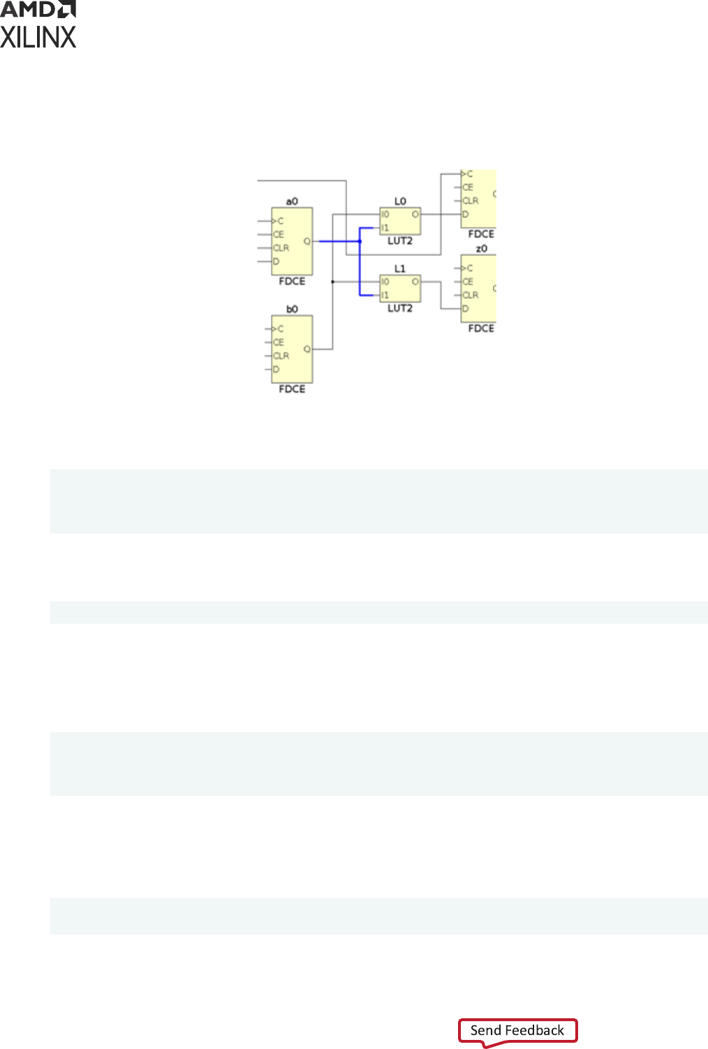
Following is an example of a fully-xed route. The example takes the design in the following
gure and creates the constraints to x the roung of the net netA (selected in blue).
Figure 95: Simple Design to Illustrate Routing Constraints
You can query the roung informaon of any net aer loading the implemented design in
memory:
% set net [get_nets netA]
% get_property ROUTE $net
{ CLBLL_LL_CQ CLBLL_LOGIC_OUTS6 FAN_ALT5 FAN_BOUNCE5 { IMUX_L17
CLBLL_LL_B3 } IMUX_L11 CLBLL_LL_A4 }
The roung is dened as a series of relave roung node names with fanout denoted using
embedded curly braces. The roung is xed by seng the following property on the net:
% set_property IS_ROUTE_FIXED TRUE $net
To back-annotate the constraints in your XDC le for future runs, the placement of all the cells
connected to the xed net must also be preserved. You can query this informaon by selecng
the cells in the schemacs or device view, and look at their LOC/BEL property values in the
Properes window. Or, you can query those values directly from the Tcl Console:
% get_property LOC [get_cells {a0 L0 L1}] SLICE_X0Y47 SLICE_X0Y47
SLICE_X0Y47
% get_property BEL [get_cells {a0 L0 L1}] SLICEL.CFF SLICEL.A6LUT
SLICEL.B6LUT
Because xed routes are oen ming-crical, LUT pins mapping must also be captured in the
LOCK_PINS property of the LUT to prevent the router from swapping pins.
Again, you can query the site pin of each logical pin from the Tcl Console:
% get_site_pins -of [get_pins {L0/I1 L0/I0}] SLICE_X0Y47/A4 SLICE_X0Y47/A2
% get_site_pins -of [get_pins {L1/I1 L1/I0}] SLICE_X0Y47/B3 SLICE_X0Y47/B2
Chapter 8: Physical Constraints
UG903 (v2022.1) June 1, 2022 www.xilinx.com
Using Constraints 155

The complete XDC constraints required to x the roung of net netA are:
set_property BEL CFF [get_cells a0] set_property BEL A6LUT [get_cells L0]
set_property BEL B6LUT [get_cells L1]
set_property LOC SLICE_X0Y47 [get_cells {a0 L0 L1}] set_property LOCK_PINS
{I1:A4 I0:A2} [get_cells L0] set_property LOCK_PINS {I1:A3 I0:A2}
[get_cells L1]
set_property FIXED_ROUTE { CLBLL_LL_CQ CLBLL_LOGIC_OUTS6 FAN_ALT5
FAN_BOUNCE5 {
IMUX_L17 CLBLL_LL_B3 } IMUX_L11 CLBLL_LL_A4 } [get_nets netA]
If you are using interacve Tcl commands instead of XDC, several placement constraints can be
specied at once with the place_cell command, as shown below:
place_cell a0 SLICE_X0Y47/CFF L0 SLICE_X0Y47/A6LUT L1 SLICE_X0Y47/B6LUT
For more informaon on place_cell, see the Vivado Design Suite Tcl Command Reference Guide
(UG835).
Configuration Constraints
Conguraon constraints are global constraints for bitstream generaon that are applied to the
current design. This includes constraints such as the conguraon mode.
Configuration Constraint Example One
Set the CONFIG_MODE to M_SELECTMAP.
% set_property CONFIG_MODE M_SELECTMAP [current_design]
Configuration Constraint Example Two
Turn on the debug bitstream.
% set_property BITSTREAM.GENERAL.DEBUGBITSTREAM Yes [current_design]
Configuration Constraint Example Three
Disable CRC checking.
% set_property BITSTREAM.GENERAL.CRC Disable [current_design]
For a list of bitstream generaon properes and denions, see this link in the Vivado Design
Suite User Guide: Programming and Debugging (UG908).
Chapter 8: Physical Constraints
UG903 (v2022.1) June 1, 2022 www.xilinx.com
Using Constraints 156

Chapter 9
Defining Relatively Placed Macros
About Relatively Placed Macros
A Relavely Placed Macro (RPM) is a list of basic logic elements (BELs) grouped into a set.
Examples of logic elements include:
• FF
• LUT
• DSP
• RAM
RPMs are primarily used to place small groups of logic close together in order to improve
resource eciency and enable faster interconnecons.
Defining Sets of Design Elements
Dene sets of design elements with U Set (U_SET) or HU Set (HU_SET) constraints.
• Each element of the set is placed in relaon to the other elements of the set by Relave
Locaon (RLOC) constraints.
• Logic elements with RLOC constraints and common set names are associated in an RPM.
U_SET, HU_SET, and RLOC constraints:
• Must be dened as properes in the HDL design les.
• Are not supported in Xilinx
®
Design Constraints format (XDC).
TIP:
You can use the
create_macro
and
update_macro
commands to dene macro objects in the
Vivado
®
Design Suite, that act like RPMs within the design. Refer to XDC Macros.
For more informaon on U_SET, HU_SET, and RLOC constraints, see the Vivado Design Suite
Properes Reference Guide (UG912).
Chapter 9: Defining Relatively Placed Macros
UG903 (v2022.1) June 1, 2022 www.xilinx.com
Using Constraints 157

Creating an RPM
To create an RPM:
1. Group cells into a set.
2. Dene relave locaons for cells in the RPM set.
3. Specify an RLOC_ORIGIN constraint or a LOC constraint on an RPM cell to x placement of
the RPM on the target device.
Note: This step is oponal.
Assigning Cells to RPM Sets
Design elements in a hierarchical module that are assigned RLOC constraints are automacally
grouped into an RPM set.
The grouping occurs by using an H_SET constraint that is implicitly dened by the combinaon of
the design hierarchy and the RLOC constraint.
All design elements with RLOC constraints in a single block of the design hierarchy are
considered to be in the same H_SET unless they are tagged with another set constraint, such as
U_SET or HU_SET.
Explicitly Grouping Design Elements
While H_SET is implied based on the design hierarchy and the presence of the RLOC constraint,
you can also explicitly group design elements into RPM sets using the U_SET and HU_SET
constraints.
Explicitly Grouping Design Elements With U_SET
U_SET lets you group cells regardless of hierarchy or where they appear in the design. All cells
with the same set_name are members of the same RPM set.
Design elements tagged with a U_SET constraint can be primive or non-primive symbols.
When aached to non-primive symbols, the U_SET constraint propagates downward through
the hierarchy to all the primive symbols below it that are assigned RLOC constraints.
Chapter 9: Defining Relatively Placed Macros
UG903 (v2022.1) June 1, 2022 www.xilinx.com
Using Constraints 158

Explicitly Grouping Design Elements With HU_SET
HU_SET has an explicit user-dened and hierarchically qualied name for the set. This lets you
create hierarchical RPMs in which RLOC constraints can be placed on cells at dierent levels of
the hierarchy.
All cells with the same hierarchically qualied set_name are members of the same set.
Syntax for Defining RPM Sets in VHDL
The syntax for dening RPM sets as aributes in VHDL is:
attribute U_SET : string;
attribute HU_SET : string;
...
attribute U_SET of my_reg : label is "uset0";
attribute HU_SET of other_reg : label is "huset0";
Syntax for Defining RPM Sets in Verilog
The syntax for dening RPM sets as aributes in Verilog is as follows.
U_SET Example
(* U_SET = "uset0", RLOC = "X0Y0" *) FD my_reg (.C(clk), .D(d0), .Q(q0));
HU_SET Example
(* HU_SET = "huset0", RLOC = "X0Y0" *) FD other_reg
(.C(clk), .D(d1), .Q(q1));
RECOMMENDED:
When using H_SET and HU_SET RPMs with Vivado Synthesis, preserve the
hierarchical boundary of the module or instance containing the RPMs. This avoids naming collisions
between RPMs at the same hierarchical level as a result of hierarchy being dissolved. For further
informaon on hierarchy preservaon see the Vivado Design Suite User Guide: Synthesis (UG901).
Chapter 9: Defining Relatively Placed Macros
UG903 (v2022.1) June 1, 2022 www.xilinx.com
Using Constraints 159
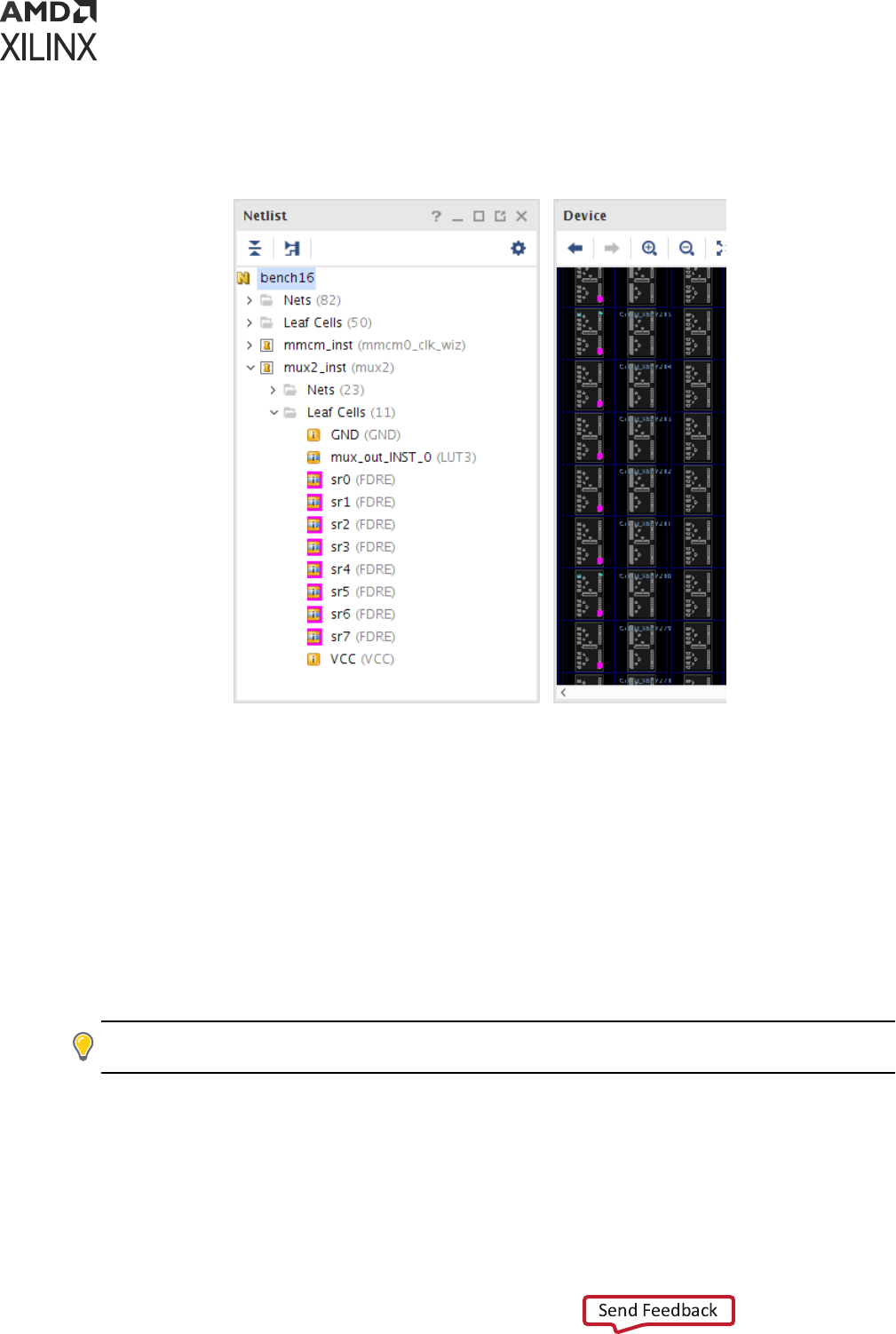
RPM Definition in the Physical Constraints Window
Figure 96: RPM Definition in the Physical Constraints Window
RPM sets must be embedded as
properes in HDL source les. Aer synthesis, RPM related
properes appear on netlist objects as read only properes for use by the Xilinx Vivado
Integrated Design Environment (IDE) placer.
Viewing RPM Definitions
View RPM denions in the Physical Constraints window. See Figure 96. To view RPM
denions:
1. Expand the RPM folder to display a list of RPMs.
2. Select an RPM to view its properes or to select related cells.
TIP:
RPMs can be placed and locked down by dragging from the Physical Constraints to the Device
window. The RPMs are moved as a single shape instead of cell-by-cell.
Chapter 9: Defining Relatively Placed Macros
UG903 (v2022.1) June 1, 2022 www.xilinx.com
Using Constraints 160

Preserving RPM through opt_design
opt_design is free to opmize and remove some LUTs that belong to an RPM despite the
RLOC constraint. To prevent opt_design from opmizing the logic inside an RPM, it is
necessary to set the property DONT_TOUCH to TRUE on all the cells that belong to the RPM.
The DONT_TOUCH property can be set either through RTL or XDC.
Assigning Relative Locations
Use the RLOC property to assign relave locaons to design objects. The RLOC property
species relave X-Y coordinates for each cell in the RPM set.
To specify the RLOC property, use either of two dierent grid coordinate systems:
• Relave Slice-Based Coordinates
• Absolute RPM Grid-Based Coordinates
Use the following syntax:
RLOC=XmYn
where
• m is an integer represenng the relave or absolute X coordinate of the object.
• n is an integer represenng the relave or absolute Y coordinate of the object.
Relative Slice-Based Coordinates
The relave grid system:
• Is also known as the standard grid.
• Is sucient for most RPMs.
• Is used for homogeneous RPMs in which all cells in an RPM belong to the same site type (such
as slice, block RAM, and DSP).
Note: Objects are posioned in relaon to other objects in the same RPM set.
Chapter 9: Defining Relatively Placed Macros
UG903 (v2022.1) June 1, 2022 www.xilinx.com
Using Constraints 161

The relave grid is a standard rectangular grid in which each grid element is the same size. For
example, the following Verilog code example results in an eight-slice-high column with an FD cell
in each slice:
(* RLOC = "X0Y0" *) FD sr0 (.C(clk), .D(d[0]), .Q(y[0]));
(* RLOC = "X0Y1" *) FD sr1 (.C(clk), .D(d[1]), .Q(y[1]));
(* RLOC = "X0Y2" *) FD sr2 (.C(clk), .D(d[2]), .Q(y[2]));
(* RLOC = "X0Y3" *) FD sr3 (.C(clk), .D(d[3]), .Q(y[3]));
(* RLOC = "X0Y4" *) FD sr4 (.C(clk), .D(d[4]), .Q(y[4]));
(* RLOC = "X0Y5" *) FD sr5 (.C(clk), .D(d[5]), .Q(y[5]));
(* RLOC = "X0Y6" *) FD sr6 (.C(clk), .D(d[6]), .Q(y[6]));
(* RLOC = "X0Y7" *) FD sr7 (.C(clk), .D(d[7]), .Q(y[7]));
BEL/LOC Constraints
For complex structures, the BEL or LOC constraints may need to be specied in addion to the
RLOC. The BEL constraint must be used to align the cells inside the RPM set, for example, to
align the LUTs with the registers. The LOC constraint is uncommon and typically not used
because the RPM set is forced on a specic site in the device and cannot be moved by the placer.
Whenever some BEL or LOC constraints need to be specied, it is important to not mix the
source of those constraints. The BEL/LOC constraints should be enrely specied either through
RTL or through XDC, but not a combinaon of both. Following is an example of BEL constraints
specied at the RTL.
Verilog le:
(*BEL="H6LUT",RLOC="X0Y0"*) LUT6 S0_LUTH (...);
(*BEL="G6LUT",RLOC="X0Y0"*) LUT6 S0_LUTG (...);
(*BEL="F6LUT",RLOC="X0Y0"*) LUT4 S0_LUTF (...);
(*BEL="E5LUT",RLOC="X0Y0"*) LUT4 S0_LUTE (...);
(*BEL="D6LUT",RLOC="X0Y0"*) LUT6 S0_LUTD (...);
(*BEL="C6LUT",RLOC="X0Y0"*) LUT6 S0_LUTC (...);
(*BEL="B6LUT",RLOC="X0Y0"*) LUT4 S0_LUTB (...);
(*BEL="A5LUT",RLOC="X0Y0"*) LUT4 S0_LUTA (...);
(*BEL="CARRY8",RLOC="X0Y0"*) CARRY8#(.CARRY_TYPE("DUAL_CY4"))
S0_CARRY8(...);
(*BEL="HFF2",RLOC="X0Y0"*) FD FD_out5 (...);
(*BEL="GFF2",RLOC="X0Y0"*) FD FD_out4 (...);
(*BEL="FFF2",RLOC="X0Y0"*) FD FD_out3 (...);
(*BEL="DFF2",RLOC="X0Y0"*) FD FD_out2 (...);
(*BEL="CFF2",RLOC="X0Y0"*) FD FD_out1 (...);
(*BEL="BFF2",RLOC="X0Y0"*) FD FD_out0 (...);
Note: The INIT string has been omied for simplicaon.
In the following example, the RPM is dened at the RTL but the BEL constraints are specied
through XDC.
Chapter 9: Defining Relatively Placed Macros
UG903 (v2022.1) June 1, 2022 www.xilinx.com
Using Constraints 162

Verilog le:
(*RLOC="X0Y0"*) LUT6 S0_LUTH (...);
(*RLOC="X0Y0"*) LUT6 S0_LUTG (...);
(*RLOC="X0Y0"*) LUT4 S0_LUTF (...);
(*RLOC="X0Y0"*) LUT4 S0_LUTE (...);
(*RLOC="X0Y0"*) LUT6 S0_LUTD (...);
(*RLOC="X0Y0"*) LUT6 S0_LUTC (...);
(*RLOC="X0Y0"*) LUT4 S0_LUTB (...);
(*RLOC="X0Y0"*) LUT4 S0_LUTA (...);
(*RLOC="X0Y0"*) CARRY8#(.CARRY_TYPE("DUAL_CY4")) S0_CARRY8(...);
(*RLOC="X0Y0"*) FD FD_out5 (...);
(*RLOC="X0Y0"*) FD FD_out4 (...);
(*RLOC="X0Y0"*) FD FD_out3 (...);
(*RLOC="X0Y0"*) FD FD_out2 (...);
(*RLOC="X0Y0"*) FD FD_out1 (...);
(*RLOC="X0Y0"*) FD FD_out0 (...);
Note: The INIT string has been omied for simplicaon.
XDC le:
set_property BEL CARRY8 [get_cells S0_CARRY8]
set_property BEL HFF2 [get_cells FD_out5]
set_property BEL GFF2 [get_cells FD_out4]
set_property BEL FFF2 [get_cells FD_out3]
set_property BEL DFF2 [get_cells FD_out2]
set_property BEL CFF2 [get_cells FD_out1]
set_property BEL BFF2 [get_cells FD_out0]
set_property BEL A5LUT [get_cells S0_LUTA]
set_property BEL B6LUT [get_cells S0_LUTB]
set_property BEL C6LUT [get_cells S0_LUTC]
set_property BEL D6LUT [get_cells S0_LUTD]
set_property BEL E5LUT [get_cells S0_LUTE]
set_property BEL F6LUT [get_cells S0_LUTF]
set_property BEL G6LUT [get_cells S0_LUTG]
set_property BEL H6LUT [get_cells S0_LUTH]
Absolute RPM Grid-Based Coordinates
The RPM_GRID system is used for heterogeneous RPMs in which cells in an RPM belong to
dierent site types (such as a combinaon of slice, block RAM, and DSP). This is an absolute
coordinate system that is mapped to a specic Xilinx device.
Because the cells can occupy sites of various sizes, the RPM_GRID system uses absolute
RPM_GRID coordinates. The RPM_GRID values are visible in the Site Properes window of the
Vivado IDE when a specic site is selected. The coordinates can also be queried with Tcl
commands using the RPM_X and RPM_Y site properes.
RPM_GRID Coordinates VHDL Example
The following VHDL example denes RLOC constraints using RPM_GRID coordinates.
Chapter 9: Defining Relatively Placed Macros
UG903 (v2022.1) June 1, 2022 www.xilinx.com
Using Constraints 163

• Two shi registers are placed relave to a block RAM.
• Four stages connect the input.
• Four stages connect the output.
attribute RLOC : string;
attribute RPM_GRID : string;
attribute RLOC of di_reg3 : label is "X25Y0";
attribute RLOC of di_reg2 : label is "X27Y0";
attribute RLOC of di_reg1: label is "X29Y0";
attribute RLOC of di_reg0 : label is "X31Y0";
attribute RLOC of ram0 : label is "X34Y0";
attribute RLOC of out_reg3 : label is "X37Y0";
attribute RLOC of out_reg2 : label is "X39Y0";
attribute RLOC of out_reg1 : label is "X41Y0";
attribute RLOC of out_reg0 : label is "X43Y0";
Setting a Property to Invoke the RPM_GRID System
To use the RPM_GRID system, set a property on any cell in the RPM set:
attribute RPM_GRID of ram0 : label is "GRID";
As long as at least one cell has the RPM_GRID property equal to GRID, the RPM_GRID
coordinate system is used.
Although the RPM_GRID coordinates are absolute based on the target device, they dene the
relave placement of the elements of an RPM set.
During implementaon, the RPM set can be placed at any suitable locaon on the device.
RPM_GRID Coordinate Values
The RPM_GRID coordinate values dier signicantly from the coordinate values of the SLICEs on
the FPGA. These coordinates:
• Are stored as RPM_X and RPM_Y properes on device sites in the Vivado tools.
• Can be queried using get_property.
The following example does the following:
• Gets the RPM coordinates from a selected SLICE.
• Uses join to output both the X and Y coordinates in the required format.
join "X[get_property RPM_X [get_selected_objects]]Y[get_property RPM_Y
[get_selected_objects]]"
X25Y394
Chapter 9: Defining Relatively Placed Macros
UG903 (v2022.1) June 1, 2022 www.xilinx.com
Using Constraints 164
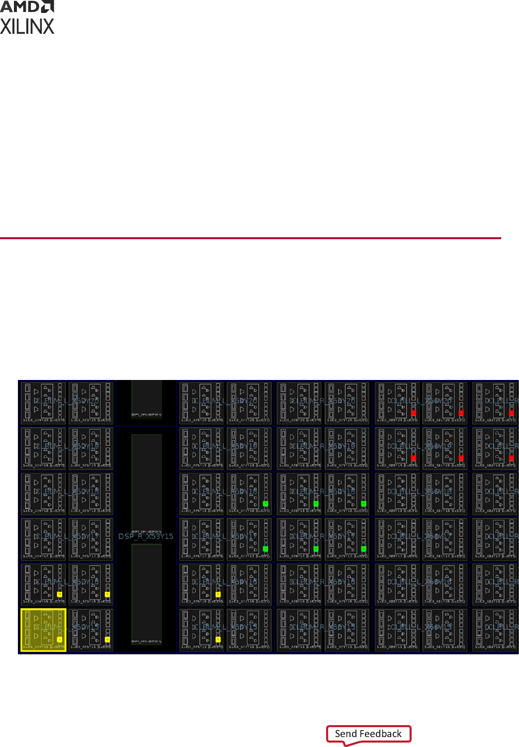
Defining RLOC Properties Directly in the RTL Source File
Because the standard grid is simple and relave, you can dene the RLOC properes for an RPM
directly in the RTL source le.
Because the RPM_GRID coordinates must be extracted from the target device, you will probably
need to:
• Iterate on the design to nd the right RPM_GRID values aer synthesis.
• Add the coordinates as properes in the RTL source les.
• Resynthesize the netlist before placement.
Assigning a Fixed Location to an RPM
Oponally use an RLOC_ORIGIN or LOC constraint to place and x the locaon of an RPM on
the device. In the Vivado IDE, these properes x the RPM origin, or the lower-le corner of the
RPM. Each remaining cell in the RPM set is placed by using the relave locaon (RLOC) to oset
from the origin.
Figure 97: RPM Placement by RLOC_ORIGIN
Chapter 9: Defining Relatively Placed Macros
UG903 (v2022.1) June 1, 2022 www.xilinx.com
Using Constraints 165
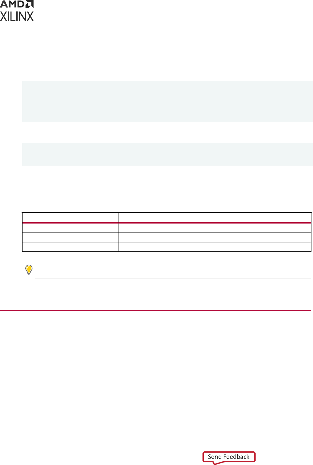
The following example shows a hierarchical RPM that is xed using RLOC_ORIGIN. RLOC
constraints are assigned to the RPM register cells to create a two-up-by-three-across placement
paern.
In Verilog:
(* RLOC = "X0Y0" *) FDC sr0...
(* RLOC = "X1Y0" *) FDC sr1...
(* RLOC = "X2Y0" *) FDC sr2...
(* RLOC = "X0Y1" *) FDC sr3...
(* RLOC = "X1Y1" *) FDC sr4...
(* RLOC = "X2Y1" *) FDC sr5...
The RPM is instanated into the design three mes with an RLOC on each cell:
(* RLOC = "X0Y0" *) ffs u0...
(* RLOC = "X3Y2" *) ffs u1...
(* RLOC = "X6Y4" *) ffs u2...
Finally, an RLOC_ORIGIN of X74Y15 is assigned to cell u0 resulng in the placement shown in
Figure 97. The highlighng in the gure is shown in the following table.
Table 11: Cell Highlighting
Cell Highlight Color
u0 yellow
u1 green
u2 red
TIP: Although RPMs control the relave placement of logic elements, they do not insure that specic
roung resources are used to connect the logic from one implementaon to the next.
For more informaon on controlling the roung used, see Roung Constraints.
XDC Macros
XDC macros enable assignment of relave placement to cells aer synthesis. Macros have many
characteriscs similar to RPMs, but are design objects that can be modied interacvely using
XDC and Tcl. Macros are created from leaf cells that are grouped together with relave
placement constraints.
While RPMs are managed in HDL code, macros are managed using XDC constraints. RPMs
cannot be automacally converted to macros. Similarly, macros cannot be automacally
annotated to HDL code. Unlike macros, RPMs are not objects, and the XDC macro commands
cannot be used on RPMs.
Chapter 9: Defining Relatively Placed Macros
UG903 (v2022.1) June 1, 2022 www.xilinx.com
Using Constraints 166

Table 12: Differences between RPMs and Macros
RPMs Macros
Definition HDL Attributes XDC constraints
Post-Synthesis
Access
Read-only Read-write
Hierarchical Yes (H_SET/HU_SET) No
RLOC Targets Non-leaf and leaf
cells
Leaf cells only
Site Type Mixing
Allowed
Yes, using
RPM_GRID attribute
Yes, using
update_macro -absolute_grid
Accessible as
objects
No Yes
Where stored In netlist In XDC or Tcl scripts
Specifying Macros
Use the following XDC Tcl commands to specify macros:
• create_macro
• update_macro
• delete_macros
• get_macros
Each command is supported by undo and redo. Following are descripons of each command.
create_macro
The create_macro command creates a new macro object.
Macro names must be unique. Aempng to create a macro with the same name as an exisng
macro generates an error.
create_macro Syntax
create_macro <name>
create_macro Example
create_macro m0
Creates a macro object called m0.
Chapter 9: Defining Relatively Placed Macros
UG903 (v2022.1) June 1, 2022 www.xilinx.com
Using Constraints 167

TIP: To ensure opmal LUT-FF alignment, specify the BEL locaon when creang your macro. The BEL
locaon must be set separately as a property on the cell objects. For example:
set_property BEL
AFF [get_cell u2/sr0]
.
update_macro
The update_macro command adds leaf cells and relave placements (RLOCs) to the macro.
The RLOC has idencal syntax and funconality as the RPM RLOC aribute. All cells must be
specied at once. No paral or incremental denion is allowed.
update_macro Syntax
update_macro [-absolute_grid] <macro name> <cell-RLOC list>
where
• -absolute_grid: A switch to choose the Absolute Grid for mixing slice and non-slice sites.
○ The X-Y values are the site properes RPM_X and RPM_Y.
○ The Absolute Grid values are idencal to those of RPM_GRID.
• macro name: The name of the macro to be updated.
• cell-RLOC list: A Tcl list of cells and RLOC pairs:
{cell0 RLOC(cell0) cell1 RLOC(cell1) - cellN RLOC(cellN)}.
○ All macro cells and RLOCs must be specied at once. It is not possible to build a macro in
steps.
○ If you need to update an exisng macro, you must re-create it rst.
update_macro Example One
update_macro m1 {u2/sr0 X0Y0 u2/sr1 X0Y1}
• Adds u2/sr0 and u2/sr1 to macro m1
• Assigns u2/sr0 an RLOC of X0Y0
• Assigns u2/sr1 an RLOC of X0Y1
The following (update_macro Example Two) does the same, with slightly dierent syntax.
update_macro Example Two
set rlocs [list u2/sr0 X0Y0 u2/sr1 X0Y1]
update_macro m1 $rlocs
Chapter 9: Defining Relatively Placed Macros
UG903 (v2022.1) June 1, 2022 www.xilinx.com
Using Constraints 168

update_macro Example Three
This example uses the absolute grid:
set rlocs {ireg X2Y38 q1reg X17Y40 q2reg X17Y40}
update_macro -absolute_grid m2 $rlocs
delete_macros
The delete_macros command deletes the specied macros.
delete_macros Syntax
delete_macros <pattern>
delete_macros Example
delete_macros m1
get_macros
The get_macros command returns macro objects in a design.
get_macros Syntax
get_macros [pattern]
With no arguments, the get_macros command returns all macros in the design. When macro
names are specied, the command returns the corresponding macro objects.
get_macros Examples
The get_macros command can be used with other object commands. Examples:
% create_macro m1
% update_macro m1 {u2/sr0 X0Y0 u2/sr1 X0Y1}
% get_cells -of [get_macros m1] u2/sr0 u2/sr1
% get_macros -of [get_cells u2] m1
The following command returns all macros that are fully contained within the cells.
get_macros -of [get_cells $cells]
Using get_cells, other indirect combinaons are possible such as:
get_macros -of [get_cells -of [get_pblocks pb0]]
This command returns the macros contained within Pblock pb0.
Chapter 9: Defining Relatively Placed Macros
UG903 (v2022.1) June 1, 2022 www.xilinx.com
Using Constraints 169

Managing Macros
Macros are stored as XDC constraints. By denion, they are Tcl commands. This allows the
macros to be used in both XDC constraint les and Tcl scripts, and used interacvely.
Macros are wrien using the write_xdc command. Macros are read using the read_xdc
command. The -cell opon can be used to limit scope to parcular cells.
The -cell opon is parcularly useful for applying a relave placement from one macro to
similar instances in dierent hierarchies.
Managing Macros Example One
Write all XDC constraints in memory, including macros:
% write_xdc constrs.xdc
Managing Macros Example Two
A design contains three instances of a cell:
inst_0, inst_1, and inst_2.
A macro is created inside inst_0:
% create_macro m0
% update_macro m0 {reg0 X0Y0 reg1 X0Y1}
% write_xdc -cell inst_0 inst_0.xdc
Managing Macros Example Three
Write all XDC constraints including macro m0, for the cell inst_0:
% write_xdc -cell inst_0.xdc inst_0.xdc
Managing Macros Example Four
Read the XDC constraints including the macro m0 from cell inst_0, and apply it to inst_1 and
inst_2:
% read_xdc inst_0 -cell {inst_1 inst_2}
% get_macros
m0 inst_1_m0 inst_2_m0
TIP:
When a macro is read and applied to another cell using the
-cell
opon, the new macro name
must be unique. The cell name is applied as a prex to the macro name to create a unique macro name. In
Example Four, two new unique macros were created. They are inst_1_m0 and inst_2_m0.
Chapter 9: Defining Relatively Placed Macros
UG903 (v2022.1) June 1, 2022 www.xilinx.com
Using Constraints 170

Macro Properties
Macro objects have the following properes:
• ABSOLUTE_GRID
• CLASS
• NAME
• RLOCS
Macro Properties Example
% report_property [get_macros m1]
Property Type Read-only Visible Value
ABSOLUTE_GRID bool true true 0
CLASS string true true macro
NAME string true true m1
RLOCS string* true true u2/sr0 X0Y0 u2/sr1 X0Y1
Following are descripons of the properes.
ABSOLUTE_GRID
Boolean property that reects whether or not the RLOCs are using the default grid system or the
Absolute Grid system.
The default is false. If update_macro is used with -absolute_grid, then the property is true.
The Absolute Grid uses coordinates that align with site RPM_X and RPM_Y properes to allow
creang macros from cells placed at dierent site types.
CLASS
Idenes the object as a macro.
NAME
Name of the macro object, either the name used by create_macro, or the macro name
prexed by the cell hierarchy when using read_xdc -cell.
RLOCS
String containing the list of macro cells and their RLOC properes in the same format used by the
update_macro command.
Macro cells have these addional properes:
• RLOC: The relave locaon property (RLOC) value of the cell.
Chapter 9: Defining Relatively Placed Macros
UG903 (v2022.1) June 1, 2022 www.xilinx.com
Using Constraints 171

• MACRO_NAME: The name of the macro to which the cell belongs.
Using the previous example for macro properes:
% get_property RLOC [get_cells {u2/sr0 u2/sr1}] X0Y0 X0Y1
% get_property MACRO_NAME [get_cells {u2/sr0 u2/sr1}] m1 m1
Preserving XDC Macros through opt_design
opt_design is free to opmize and remove LUTs that belong to an XDC macro despite the
RLOC constraint. To prevent opt_design from opmizing the logic inside an XDC macro, it is
necessary to set the property DONT_TOUCH to TRUE on all the cells that belong to the XDC
macro. The DONT_TOUCH property can be set either through RTL or XDC.
Advanced XDC Macro Examples
This secon gives the following advanced XDC macro examples:
• Relave Grid Macro Examples
• Absolute Grid Macro Examples
Relative Grid Macro Examples
By default, the relave grid is used for macro RLOC coordinates because the most common
macros are made of cells that belong to the same site type.
The following simple example illustrates the relave placement derived from macro RLOCs. The
macro consists of a pair of SRL >FF >FF circuits that are to be arranged in a 2x2 paern. See the
following gure.
Chapter 9: Defining Relatively Placed Macros
UG903 (v2022.1) June 1, 2022 www.xilinx.com
Using Constraints 172
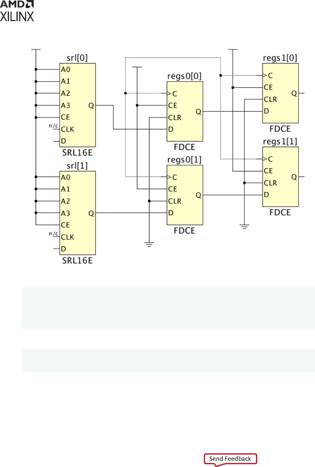
Figure 98: Schematic of Example Circuit
To create the desired relave placement, the cells are assigned RLOCs as follows:
srl[0] X0Y0
regs0[0] X0Y0
regs1[0] X1Y0
srl[1] X0Y1
regs0[1] X0Y1
regs1[1] X1Y1
The following commands create this macro with a name m0:
create_macro m0
update_macro m0 {srl[0] X0Y0 regs0[0] X0Y0 regs1[0] X1Y0 srl[1] X0Y1
regs0[1] X0Y1 regs1[1] X1Y1}
The macro can be automacally placed by the placer or manually placed as a set. The macro
placement appears as shown in the following gure:
Chapter 9: Defining Relatively Placed Macros
UG903 (v2022.1) June 1, 2022 www.xilinx.com
Using Constraints 173
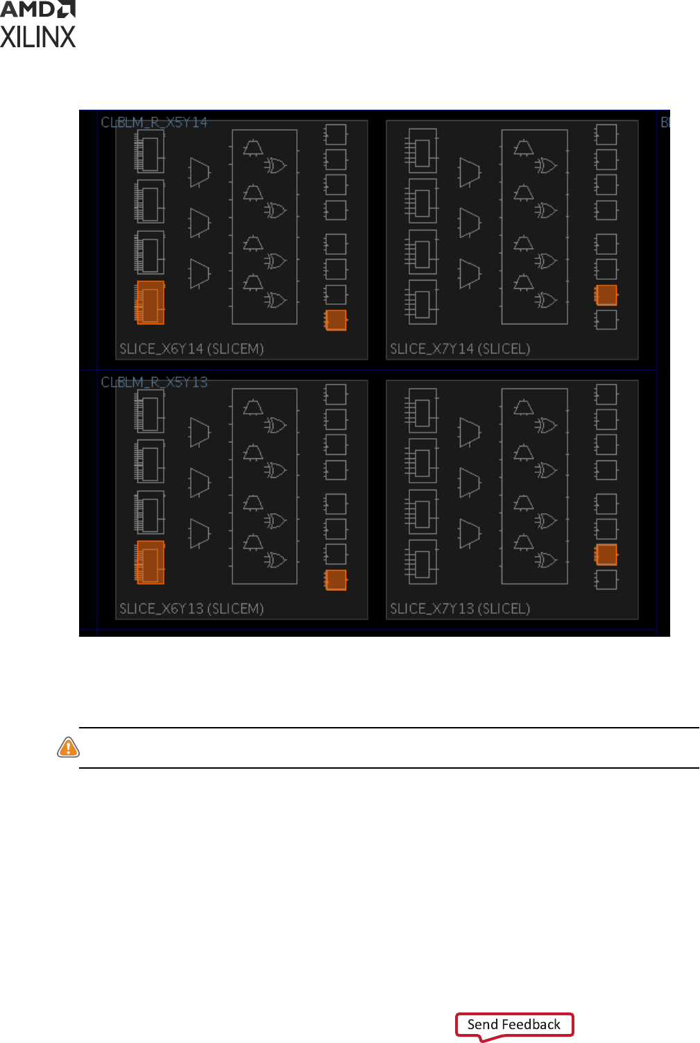
Figure 99: Placement of the Macro Example
The macro contains SRLs which are based on LUTRAMs, and which can be placed only in SLICEM
type slices. This places slight restricons on the possible locaons of the macro. The macro can
be located only where a SLICEL column is to the right of a SLICEM column.
CAUTION!
Too many densely packed slices in proximity can cause congeson, which reduces routability
and can negavely impact performance.
Absolute Grid Macro Examples
When combining cells of dierent site types into a macro, you must use the absolute grid.
The absolute grid (also known as the RPM grid) is an absolute coordinate system that denes the
coordinates of a site based on its locaon within the device. The absolute grid also considers the
sizes of sites. RAM and DSP blocks have wider spacing than slices. The absolute grid is illustrated
in the following gure:
Chapter 9: Defining Relatively Placed Macros
UG903 (v2022.1) June 1, 2022 www.xilinx.com
Using Constraints 174
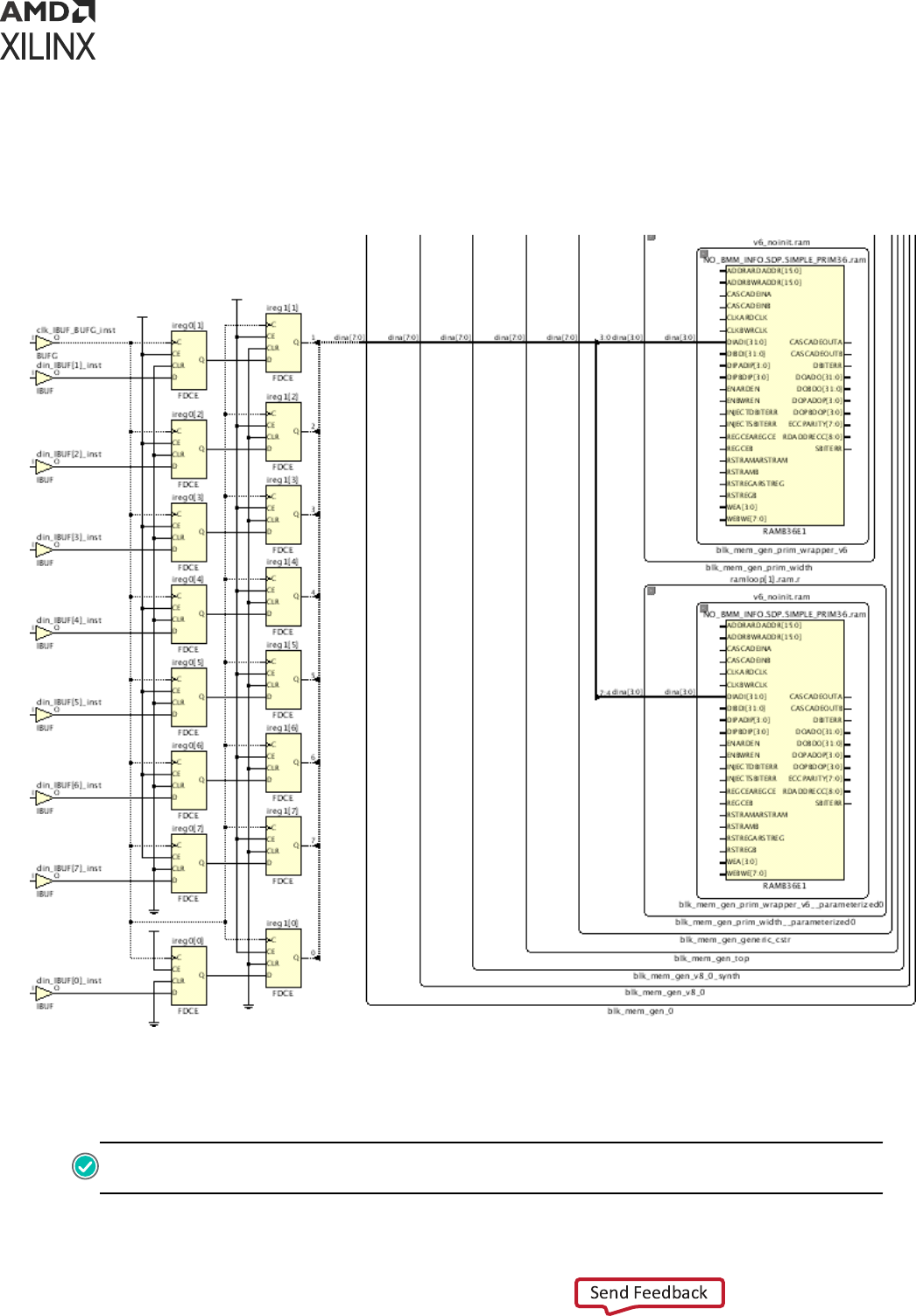
In this example, there are cells from three dierent types to group into a macro using the
absolute grid. The example consists of an input data path from input ports, through two stages of
registers, then block RAMs. This is illustrated in the schemac in the following gure.
Figure 100: Example Circuit for Absolute Grid
The macro creaon requires a list of cells and their relave locaons (RLOCs) using the absolute
grid. When creang the macro, it might be dicult to visualize the relave placement of absolute
grid macros.
RECOMMENDED:
Place the cells temporarily into absolute locaons in the device, then derive the
absolute grid RLOC values of each cell.
Chapter 9: Defining Relatively Placed Macros
UG903 (v2022.1) June 1, 2022 www.xilinx.com
Using Constraints 175
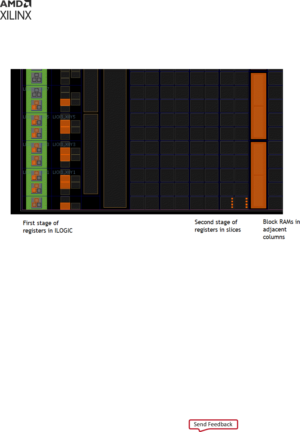
The cells are rst manually placed and arranged in their desired locaons as shown in the
following gure:
Figure 101: Manually Placed Cells for an Absolute Grid Macro
Although the absolute grid species absolute locaons, the resulng macro can be placed at any
locaon within the device that can accommodate the relave placement of the macro. In this
example, the relave locaons are specied using the lower-le hand corner as the point of
reference.
However, the absolute grid locaons specify only relave placement, not absolute placement.
That allows the macro to be located anywhere in the device that maintains the relave
placement.
Because the example is somewhat complex, consisng of ILOGIC, slices, and block RAM, the
macro locaons are somewhat restricted but can be placed at any of the three locaons
highlighted in orange in the following gure:
Chapter 9: Defining Relatively Placed Macros
UG903 (v2022.1) June 1, 2022 www.xilinx.com
Using Constraints 176
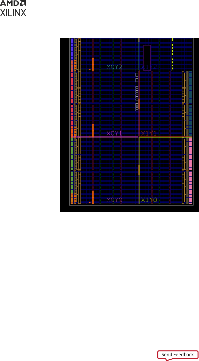
Figure 102: Three Possible Locations for the XDC Macro
To determine absolute grid RLOCs, use the site RPM_X and RPM_Y properes. For example, the
lower block RAM is placed at site RAMB36_X0Y0.
Selecng the site (not the cell) displays the following values of 33 for RPM_X and 0 for RPM_Y
(Figure 103). These are the absolute grid coordinates. The corresponding RLOC value is X33Y0.
Chapter 9: Defining Relatively Placed Macros
UG903 (v2022.1) June 1, 2022 www.xilinx.com
Using Constraints 177
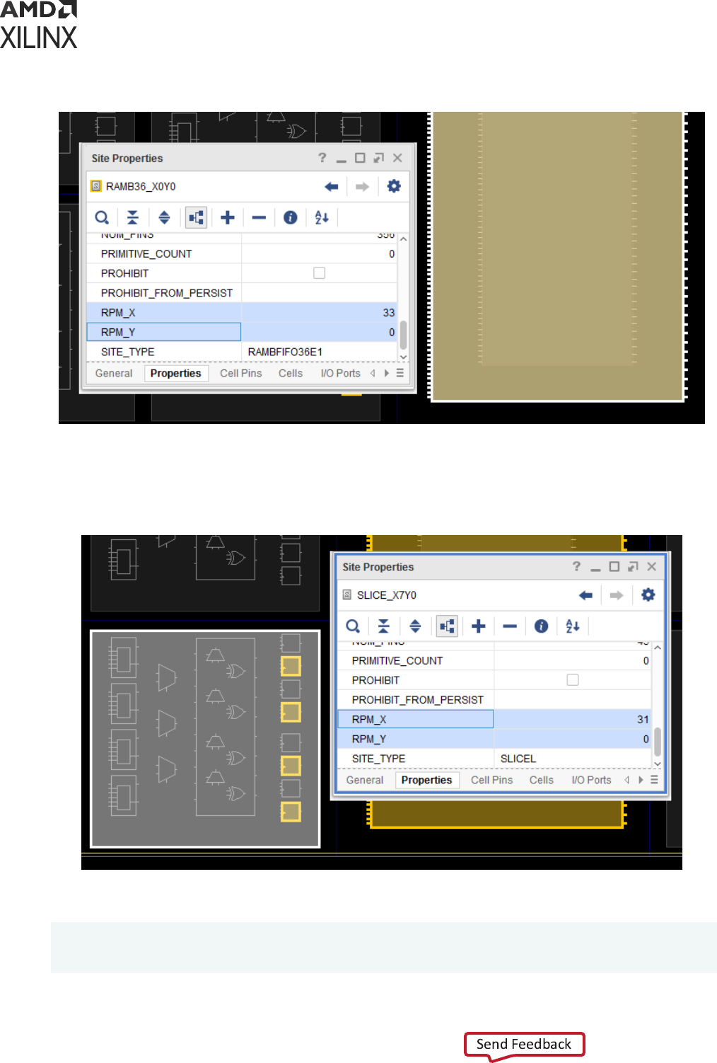
Figure 103: Absolute Grid Coordinates of a Block RAM
The same method is applied to determine the absolute RLOC of a slice (Figure 104). The cells
within this slice have an RLOC of X31Y0.
Figure 104: Absolute Grid Coordinates of a Slice
There are two commands used to create the macro, with a name m0:
create_macro m0
update_macro m0 -absolute_grid <cell0 rloc0 cell1 rloc1 cell2 rloc2 … cellN
rlocN>
Chapter 9: Defining Relatively Placed Macros
UG903 (v2022.1) June 1, 2022 www.xilinx.com
Using Constraints 178

If the macro contains many cells as it does in this example, Tcl can be used to simply building and
specifying the cell-rloc list required by update_macro. Given a placed cell, the absolute grid
RLOC can be determined using the following Tcl proc getAbsRLOC:
proc getAbsRLOC {cell} {
set site [get_sites -of [get_cells $cell]] set X [get_property RPM_X $site]
set Y [get_property RPM_Y $site] return "X${X}Y${Y}"
}
Example: Assign the Variable rloc to the String Value of a Block RAM Cell RLOC
% set rloc [getAbsRLOC $ram0]
X33Y0
The Tcl dict command can be used to build a diconary (associave array) of cells and absolute
grid RLOCs for the update_macro command. A Tcl associave array is a series of key-value
pairs. The cells and RLOCs can be arranged as such as series using the dict command. The array
keys are the macro cell objects. The array values are the cell RLOCs. This helps to automate the
process of creang macros with many cells. The following example uses the absolute grid, but
the method can be applied to the normal grid as well.
Assuming $cells is the list of macro cells, and each cell of $cells has been placed to form the
desired macro paern, the following Tcl proc creates a list of cell-RLOC pairs for the
update_macro command.
proc buildRLOCList {cells} {
set rlocs [dict create] ; # initialize dictionary called rlocs foreach cell
$cells {
# dictionary key is cell, value is absolute RLOC dict set rlocs $cell
[getAbsRLOC $cell]
}
return $rlocs
}
Example: Build an RLOC List for the Example Circuit
# create macro cell list: input register stage and BRAM cells
set cells [get_cells -hier [list ireg0* ireg1* *SIMPLE_PRIM36.ram]]
create_macro m0
update_macro m0 -absolute_grid [buildRLOCList $cells]
To see the diconary list created by buildRLOCList:
$ puts [buildRLOCList $cells]
{ireg0[6]} X2Y10 {ireg0[5]} X2Y11 {ireg0[4]} X2Y6 {ireg0[3]} X2Y7 . . .
If there are many macro cells and macro cells buried in hierarchy, specifying the explicit list of
cell-RLOC pairs can become complicated and error prone. The creaon and management of XDC
macros can be made simpler using Tcl.
Chapter 9: Defining Relatively Placed Macros
UG903 (v2022.1) June 1, 2022 www.xilinx.com
Using Constraints 179

Converting RPMs to XDC Macros
It is recommended to convert RPMs to XDC macros wherever feasible because XDC macros are
the preferred method of implemenng relave placement constraints. This process can be done
manually by removing the RPM aributes from the HDL sources and creang equivalent XDC
macros. Conversion can also be done somewhat automacally by using Tcl to replace RPM
aributes with XDC macro constraints.
The automated process consists of the following steps:
1. In all HDL sources, replace each RPM aribute with a similarly named string, for example:
• Replace hu_set with m_hu_set
• Replace u_set with m_u_set
• Replace rloc with m_rloc
This ensures that the RPMs are not processed however the inacve aributes are passed
through to the synthesized netlist as cell properes.
2. Open the synthesized design or run link_design and create XDC macros based on the
inacve properes. For example, each HU_SET will have a cell property called m_hu_set
that can be used to create the equivalent XDC macro. Each cell within the original HU_SET
will have a property m_rloc that can be converted to an RLOC.
3. Save the constraints which now include the XDC macros denions.
The conversion is best accomplished using Tcl by building XDC macros cell lists based on their
unique m_hu_set or m_uset values. Following is a simple VHDL conversion example.
The original VHDL source includes a HU_SET RPM called set0 with two cells, one with RLOC
X0Y0 and the other with RLOC X0Y1.
signal r0 : std_logic;
signal r1 : std_logic;
attribute hu_set : string;
attribute rloc : string;
attribute hu_set of r0 : signal is "set0";
attribute hu_set of r1 : signal is "set0";
attribute rloc of r0 : signal is "X0Y0";
attribute rloc of r1 : signal is "X0Y1";
Chapter 9: Defining Relatively Placed Macros
UG903 (v2022.1) June 1, 2022 www.xilinx.com
Using Constraints 180

Next the VHDL source is modied to replace hu_set and RLOC with similarly named but inacve
aributes:
signal r0 : std_logic;
signal r1 : std_logic;
attribute m_hu_set : string;
attribute m_rloc : string;
attribute m_hu_set of r0 : signal is "set0";
attribute m_hu_set of r1 : signal is "set0";
attribute m_rloc of r0 : signal is "X0Y0";
attribute m_rloc of r1 : signal is "X0Y1";
Aer synthesis, the cells can be ltered based on these similarly named properes:
Vivado% get_cells -filter {m_hu_set == "set0"}
r0_reg r1_reg
Vivado% get_property m_rloc [get_cells {r0_reg r1_reg}]
X0Y0 X0Y1
This provides the necessary informaon to create an XDC macro to replace the RPM:
Vivado% create_macro set0
Vivado% update_macro set0 {r0_reg X0Y0 r1_reg X0Y1}
These two XDC constraints can be saved as part of the design constraints. Large amounts of
RPM conversions are beer handled using a Tcl script. Following is an example script to convert
HU_SET RPMs to XDC macros.
# create a sorted list of all unique RPMs according to m_hu_set values set
RPMs [lsort -uniq [get_property m_hu_set [get_cells -hier -filter
{primitive_level != INTERNAL}]]]
# remove the first element which is empty (no m_hu_set property) set RPMs
[lrange $RPMs 1 end]
# iterate over list of RPMs, convert each to an XDC macro # get each RPM
cell of the RPM with its RLOC
# build a list for the update_macro command foreach rpm $RPMs {
create_macro $rpm
set cells [get_cells -hier -filter "m_hu_set == $rpm"] set rlocs [list]
foreach cell $cells { lappend rlocs $cell
lappend rlocs [get_property m_rloc $cell]
}
update_macro $rpm $rlocs
puts "created XDC macro $rpm, cell list: $rlocs"
}
Chapter 9: Defining Relatively Placed Macros
UG903 (v2022.1) June 1, 2022 www.xilinx.com
Using Constraints 181

Appendix A
Supported XDC and SDC Commands
This Appendix discusses supported Xilinx Design Constraints (XDC) and Synopsys Design
Constraints (SDC) commands in the Xilinx Vivado
®
Integrated Design Environment (IDE).
Valid Commands in an XDC File
Table 13: Valid Commands in an XDC File
Timing Constraint Physical Constraint General Purpose
create_clock
create_generated_clock
group_path
set_clock_groups
set_clock_latency
set_data_check
set_disable_timing
set_false_path
set_input_delay
set_output_delay
set_max_delay
set_min_delay
set_multicycle_path
set_case_analysis
set_clock_sense
set_clock_uncertainty
set_input_jitter
set_max_time_borrow
set_propagated_clock
set_system_jitter
set_external_delay
set_bus_skew
add_cells_to_pblock
create_pblock
delete_pblock
remove_cells_from_pblock
resize_pblock
create_macro
delete_macros
update_macro
set_package_pin_val
set
expr
list
filter
current_instance
get_hierarchy_separator
set_hierarchy_separator
get_property set_property
set_units
endgroup
startgroup
create_property
current_design
Debug Constraint
create_debug_core
create_debug_port
connect_debug_port
Power Constraint Netlist Constraint
set_power_opt
set_switching_activity
reset_switching_activity
set_operating_conditions
reset_operating_conditions
add_to_power_rail
create_power_rail
delete_power_rails
get_power_rails
remove_from_power_rail
set_load
set_logic_dc
set_logic_one
set_logic_zero
set_logic_unconnected
make_diff_pair_ports
Waiver Constraint
create_waiver
Device Object Query Timing Object Query Netlist Object Query
get_iobanks all_clocks all_cpus
Appendix A: Supported XDC and SDC Commands
UG903 (v2022.1) June 1, 2022 www.xilinx.com
Using Constraints 182
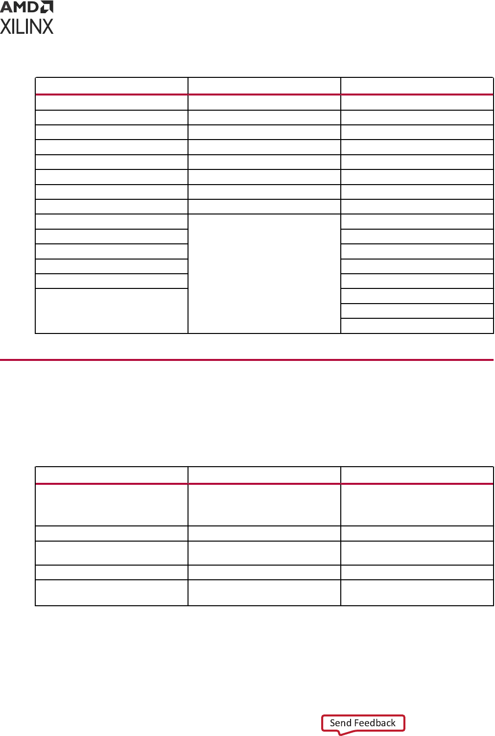
Table 13: Valid Commands in an XDC File (cont'd)
Timing Constraint Physical Constraint General Purpose
get_package_pins get_path_groups all_dsps
get_sites get_clocks all_fanin
get_bel_pins get_generated_clocks all_fanout
get_bels get_timing_arcs all_hsios
get_nodes get_speed_models all_inputs
get_pips Floorplan Object Query all_outputs
get_site_pins all_ramsget_pblocks
get_site_pips get_macros all_registers
get_slrs all_ffs
get_tiles all_latches
get_wires get_cells
get_pkgpin_bytegroups get_nets
get_pkgpin_nibbles get_pins
get_ports
get_debug_cores
get_debug_ports
Supported SDC Commands
Note: Because all Xilinx Tcl commands support the -quiet and -verbose opons, the following table
does not list them.
Table 14: Supported SDC Commands
SDC 1.9 Xilinx SDC Notes
current_instance [instance_name] current_instance [instance_name] The Vivado IDE handles get_ports
differently when using read_xdc -cells/-
ref or the SCOPED_TO_xxx constraint
file property.
expr expr
list list In the Vivado IDE, a Tcl list is also used
as an objects container.
set set
set_hierarchy_separator
[separator]
set_hierarchy_separator
[separator]
Appendix A: Supported XDC and SDC Commands
UG903 (v2022.1) June 1, 2022 www.xilinx.com
Using Constraints 183

Table 14: Supported SDC Commands (cont'd)
SDC 1.9 Xilinx SDC Notes
set_units
[-capacitance cap_units] [-resistance
res_unit]
[-time time_unit]
[-voltage voltage_units] [-current
current_unit] [-power power_unit]
set_units
[-capacitance arg] [-resistance arg] [-
time arg]
[-voltage arg] [-current arg] [-power
arg]
[-suffix arg]
[-digits arg]
The set_units -time cannot change the
timing unit in the Vivado IDE.
all_clocks all_clocks
all_inputs
[-level_sensitive] [-edge_triggered]
[-clock clock_name]
all_inputs
all_outputs
[-level_sensitive] [-edge_triggered]
[-clock clock_name]
all_outputs
all_registers all_registers
[-no_hierarchy] [-no_hierarchy]
[-clock clock_name] [-clock args]
[-rise_clock clock_name] [-rise_clock args]
[-fall_clock clock_name] [-fall_clock args]
[-cells]
[-data_pins] [-clock_pins]
[-slave_clock_pins] [-async_pins]
[-output_pins]
[-level_sensitive] [-edge_triggered] [-
master_slave]
[-cells]
[-data_pins] [-clock_pins]
[-async_pins] [-output_pins]
[-level_sensitive]
[-edge_triggered]
current_design current_design In the Vivado IDE, the current design
refers to the design loaded in memory,
and cannot be changed to another
module or entity than the top-level
one.
get_cells
get_cells
[-hierarchical] [-hsc arg]
[-regexp]
[-nocase]
[-of_objects args] [patterns]
[-filter arg]
[-match_style arg]
[-hierarchical]
[-hsc separator]
[-regexp]
[-nocase]
-of_objects objects
patterns
get_clocks
[-regexp]
[-nocase]
get_clocks [-regexp]
[-nocase] [patterns]
[-filter arg]
[-of_objects args] [-match_style arg]
[-include_generated_clocks]
The Vivado IDE supports the -of_objects
option to query the clock object on the
clock tree.
patterns
Appendix A: Supported XDC and SDC Commands
UG903 (v2022.1) June 1, 2022 www.xilinx.com
Using Constraints 184

Table 14: Supported SDC Commands (cont'd)
SDC 1.9 Xilinx SDC Notes
get_lib_cells get_lib_cells [-regexp]
[-nocase]
patterns
[-filter arg]
[-include_unsupported] [-of_objects
args]
In the Vivado IDE, because only one
device library can be loaded for a
design, it is not necessary to specify the
library name when querying the library
cells.
[-hsc separator]
[-regexp]
[-nocase]
patterns
get_lib_pins
[-hsc separator] [-regexp]
[-nocase]
patterns
get_lib_pins
[-regexp]
[-nocase]
patterns
[-filter arg]
[-of_objects args]
get_libs
[-regexp]
[-nocase]
patterns
get_libs
[-regexp]
[-nocase] [patterns]
[-filter arg]
get_nets
[-hierarchical] [-hsc separator] [-regexp]
[-nocase]
-of_objects objects patterns
get_nets
[-hierarchical] [-hsc arg]
[-regexp]
[-nocase]
[-of_objects args] [patterns]
[-filter arg]
[-match_style arg]
[-top_net_of_hierarchical_grou p]
[-segments]
[-boundary_type arg]
get_pins
[-hierarchical] [-hsc separator] [-regexp]
[-nocase]
-of_objects objects patterns
get_pins
[-hierarchical] [-hsc arg]
[-regexp]
[-nocase]
[-of_objects args] [patterns]
[-leaf]
[-filter arg]
[-match_style arg]
get_ports [-regexp]
[-nocase]
patterns
get_ports [-regexp]
[-nocase] [patterns]
[-filter arg]
[-of_objects args] [-match_style arg]
create_clock
-period period_value
[-name clock_name]
[-waveform edge_list] [-add]
[source_objects]
create_clock
-period arg
[-name arg]
[-waveform args] [-add]
[objects]
Appendix A: Supported XDC and SDC Commands
UG903 (v2022.1) June 1, 2022 www.xilinx.com
Using Constraints 185

Table 14: Supported SDC Commands (cont'd)
SDC 1.9 Xilinx SDC Notes
create_generated_clock [-name
clock_name]
-source master_pin [-edges edge_list] [-
divide_by factor]
[-multiply_by factor] [-duty_cycle
percent] [-invert]
[-edge_shift shift_list] [-add]
[-master_clock clock] [-combinational]
source_objects
create_generated_clock [-name arg]
[-source args] [-edges args]
[-divide_by arg]
[-multiply_by arg] [-duty_cycle arg]
[-edge_shift args] [-add]
[-master_clock arg] [-combinational]
objects
group_path
group_path
[-name arg]
[-weight 1|2] [-from args]
[-to args]
[-through args]
[-name group_name]
[-default]
[-weight weight_value]
[-from from_list]
[-rise_from from_list]
[-fall_from from_list]
[-to to_list]
[-rise_to to_list]
[-fall_to to_list]
[-through through_list]
[-rise_through
through_list]
[-fall_through
through_list]
set_clock_groups [-name name]
[-logically_exclusive] [-
physically_exclusive] [-asynchronous]
[-allow_paths]
-group
clock_list
set_clock_groups [-name arg]
[-logically_exclusive] [-
physically_exclusive] [-asynchronous]
[-group args]
set_clock_latency
set_clock_latency [-rise]
[-fall]
[-min]
[-max]
[-source]
[-late]
[-early]
[-clock args]
latency objects
[-rise]
[-fall]
[-min]
[-max]
[-source]
[-late]
[-early]
[-clock clock_list]
delay
object_list
Appendix A: Supported XDC and SDC Commands
UG903 (v2022.1) June 1, 2022 www.xilinx.com
Using Constraints 186

Table 14: Supported SDC Commands (cont'd)
SDC 1.9 Xilinx SDC Notes
set_clock_sense set_clock_sense [-positive]
[-negative] [-pulse arg]
[-stop_propagation] [-clocks args]
pins
[-positive]
[-negative]
[-pulse pulse]
[-stop_propagation]
[-clock clock_list]
pin_list
set_clock_uncertainty set_clock_uncertainty [-from args]
[-rise_from args] [-fall_from args] [-to
args]
[-rise_to args] [-fall_to args]
[-setup]
[-hold] uncertainty [objects]
[-from from_clock]
[-rise_from
rise_from_clock]
[-fall_from
fall_from_clock]
[-to to_clock]
[-rise_to rise_to_clock]
[-fall_to fall_to_clock]
[-rise]
[-fall]
[-setup]
[-hold]
uncertainty
[object_list]
set_data_check set_data_check [-from args] [-to args]
[-rise_from args] [-fall_from args] [-
rise_to args]
[-fall_toargs]
[-setup]
[-hold]
[-clock args] value
[-from from_object]
[-to to_object]
[-rise_from from_object]
[-fall_from from_object]
[-rise_to to_object]
[-fall_to to_object]
[-setup]
[-hold]
[-clock clock_object]
value
set_disable_timing set_disable_timing [-from arg]
[-to arg]
objects
[-from from_pin_name]
[-to to_pin_name]
cell_pin_list
Appendix A: Supported XDC and SDC Commands
UG903 (v2022.1) June 1, 2022 www.xilinx.com
Using Constraints 187

Table 14: Supported SDC Commands (cont'd)
SDC 1.9 Xilinx SDC Notes
set_false_path set_false_path
[-setup] [-setup]
[-hold] [-hold]
[-rise] [-rise]
[-fall] [-fall]
[-from from_list] [-from args]
[-to to_list] [-to args]
[-through through_list] [-through args]
[-rise_from
rise_from_list]
[-rise_from args]
[-rise_to args]
[-rise_to rise_to_list] [-rise_through args]
[-rise_through
rise_through_list]
[-fall_from
fall_from_list]
[-fall_from args] [-fall_to args]
[-fall_to fall_to_list] [-fall_through args]
[-fall_through
fall_through_list]
[-reset_path]
set_input_delay
[-clock clock_name] [-clock_fall]
set_input_delay [-clock args]
[-clock_fall]
In the Vivado IDE, input delays are not
supported on internal pins.
[-level_sensitive]
[-rise] [-rise]
[-fall] [-fall]
[-max] [-max]
[-min] [-min]
[-add_delay] [-add_delay]
[-network_latency_included]
[-network_latency_included
]
[-source_latency_included]
delay
[-source_latency_included] objects
delay_value [-reference_pin args]
port_pin_list
Appendix A: Supported XDC and SDC Commands
UG903 (v2022.1) June 1, 2022 www.xilinx.com
Using Constraints 188

Table 14: Supported SDC Commands (cont'd)
SDC 1.9 Xilinx SDC Notes
set_max_delay set_max_delay
[-rise] [-rise]
[-fall] [-fall]
[-from from_list] [-from args]
[-to to_list] [-to args]
[-through through_list] [-through args]
[-rise_from
rise_from_list]
[-rise_from args]
[-rise_to args]
[-rise_to rise_to_list] [-rise_through args]
[-rise_through
rise_through_list]
[-fall_from
fall_from_list]
[-fall_from args] [-fall_to args]
[-fall_to fall_to_list] [-fall_through args]
[-fall_through
fall_through_list]
delay
delay_value [-reset_path]
[-datapath_only]
set_max_time_borrow
delay_value object_list
set_max_time_borrow
delay objects
set_min_delay set_min_delay
[-rise] [-rise]
[-fall] [-fall]
[-from from_list] [-from args]
[-to to_list] [-to args]
[-through through_list] [-through args]
[-rise_from
rise_from_list]
[-rise_from args]
[-rise_to args]
[-rise_to rise_to_list] [-rise_through args]
[-rise_through
rise_through_list]
[-fall_from
fall_from_list]
[-fall_to args]
[-fall_from args]
[-fall_to fall_to_list] [-fall_through args]
[-fall_through
fall_through_list]
delay
delay_value [-reset_path]
Appendix A: Supported XDC and SDC Commands
UG903 (v2022.1) June 1, 2022 www.xilinx.com
Using Constraints 189

Table 14: Supported SDC Commands (cont'd)
SDC 1.9 Xilinx SDC Notes
set_multicycle_path set_multicycle_path
[-setup] [-setup]
[-hold] [-hold]
[-rise] [-rise]
[-fall] [-fall]
[-start] [-start]
[-end] [-end]
[-from from_list] [-from args]
[-to to_list] [-to args]
[-through through_list] [-through args]
[-rise_from
rise_from_list]
[-rise_from args]
[-rise_to args]
[-rise_to rise_to_list] [-rise_through args]
[-rise_through
rise_through_list]
[-fall_from
fall_from_list]
[-fall_from args] [-fall_to args]
[-fall_to fall_to_list] [-fall_through args]
[-fall_through
fall_through_list]
path_multiplier
path_multiplier [-reset_path]
set_output_delay
[-clock clock_name] [-clock_fall]
set_output_delay [-clock args]
[-clock_fall]
In the Vivado IDE, output delays are not
supported on internal pins.
[-level_sensitive]
[-rise] [-rise]
[-fall] [-fall]
[-max] [-max]
[-min] [-min]
[-add_delay] [-add_delay]
[-network_latency_included]
[-network_latency_included
]
[-source_latency_included]
delay
[-source_latency_included] objects
delay_value [-reference_pin args]
port_pin_list
set_propagated_clock
object_list
set_propagated_clock
object
In the Vivado IDE, all clocks are
propagated clocks by default.
set_case_analysis
value port_or_pin_list
set_case_analysis
value objects
Appendix A: Supported XDC and SDC Commands
UG903 (v2022.1) June 1, 2022 www.xilinx.com
Using Constraints 190

Table 14: Supported SDC Commands (cont'd)
SDC 1.9 Xilinx SDC Notes
set_load [-min]
[-max]
set_load [-max]
[-min]
In the Vivado IDE, the set_load
command is relevant for power
analysis only.
[-subtract_pin_load]
[-pin_load]
[-wire_load]
value capacitance
objects objects
[-rise]
[-fall]
set_logic_dc
port_list
set_logic_dc
objects
set_logic_one
port_list
set_logic_one
objects
set_logic_zero
port_list
set_logic_zero
objects
set_operating_conditions set_operating_conditions In the Vivado IDE, the
set_operating_conditions command: (1)
sets the operating conditions for power
analysis only; and (2) does not
influence the timing reports. The
Vivado IDE timing engine is controlled
by the config_timing_analysis
command. For more information on
config_timing_analysis see the Vivado
Design Suite Tcl Command Reference
Guide (UG835).
[-library lib_name]
[-analysis_type
analysis_type]
[-max max_condition]
[-min min_condition]
[-max_library max_lib]
[-min_library min_lib]
[-object_list objects]
[condition] [-voltage args]
[-grade arg]
[-process arg]
[-junction_temp arg]
[-ambient_temp arg]
[-thetaja arg]
[-thetasa arg]
[-airflow arg]
[-heatsink arg]
[-thetajb arg]
[-board arg]
[-board_temp arg]
[-board_layers arg]
Appendix A: Supported XDC and SDC Commands
UG903 (v2022.1) June 1, 2022 www.xilinx.com
Using Constraints 191

Unsupported SDC Commands
The following SDC commands are not supported.
• set_clock_gating_check
• set_clock_transition
• set_ideal_latency
• set_ideal_network
• set_ideal_transition
• set_max_fanout
Note: Maximum fanout is controlled by the MAX_FANOUT aribute during synthesis.
• set_drive
• set_driving_cell
• set_fanout_load
• set_input_transition
• set_max_area
• set_max_capacitance
• set_max_transition
• set_min_capacitance
• set_port_fanout_number
• set_resistance
• set_timing_derate
• set_voltage
• set_wire_load_min_block_size
• set_wire_load_mode
• set_wire_load_model
• set_wire_load_selection_group
• create_voltage_area
• set_level_shifter_strategy
• set_level_shifter_threshold
• set_max_dynamic_power
Appendix A: Supported XDC and SDC Commands
UG903 (v2022.1) June 1, 2022 www.xilinx.com
Using Constraints 192


Appendix B
Additional Resources and Legal
Notices
Xilinx Resources
For support resources such as Answers, Documentaon, Downloads, and Forums, see Xilinx
Support.
Solution Centers
See the Xilinx Soluon Centers for support on devices, soware tools, and intellectual property
at all stages of the design cycle. Topics include design assistance, advisories, and troubleshoong
ps.
Documentation Navigator and Design Hubs
Xilinx
®
Documentaon Navigator (DocNav) provides access to Xilinx documents, videos, and
support resources, which you can lter and search to nd informaon. To open DocNav:
• From the Vivado
®
IDE, select Help → Documentaon and Tutorials.
• On Windows, select Start → All Programs → Xilinx Design Tools → DocNav.
• At the Linux command prompt, enter docnav.
Xilinx Design Hubs provide links to documentaon organized by design tasks and other topics,
which you can use to learn key concepts and address frequently asked quesons. To access the
Design Hubs:
• In DocNav, click the Design Hubs View tab.
• On the Xilinx website, see the Design Hubs page.
Appendix B: Additional Resources and Legal Notices
UG903 (v2022.1) June 1, 2022 www.xilinx.com
Using Constraints 194

Note: For more informaon on DocNav, see the Documentaon Navigator page on the Xilinx website.
References
Vivado Design Suite User and Reference Guides
The following Vivado
®
Design Suite guides are referenced in this document.:
1. ISE to Vivado Design Suite Migraon Guide (UG911)
2. Vivado Design Suite User Guide: System-Level Design Entry (UG895)
3. Vivado Design Suite User Guide: I/O and Clock Planning (UG899)
4. Vivado Design Suite User Guide: Design Analysis and Closure Techniques (UG906)
5. UltraFast Design Methodology Guide for Xilinx FPGAs and SoCs (UG949)
6. AXI Quad SPI LogiCORE IP Product Guide (PG153)
7. Vivado Design Suite User Guide: Using the Vivado IDE (UG893)
8. Vivado Design Suite User Guide: Synthesis (UG901)
9. Vivado Design Suite User Guide: Implementaon (UG904)
10. Vivado Design Suite Tcl Command Reference Guide (UG835)
11. Vivado Design Suite Properes Reference Guide (UG912)
12. Vivado Design Suite User Guide: Programming and Debugging (UG908)
13. 7 Series FPGAs SelectIO Resources User Guide (UG471)
Additional Xilinx Resources
The following addional resources are referenced in this document:
1. Xilinx Answer Record 59893
Training Resources
Xilinx provides a variety of training courses and QuickTake videos to help you learn more about
the concepts presented in this document. Use these links to explore related training resources:
1. Designing FPGAs Using the Vivado Design Suite 1 Training Course
2. Designing FPGAs Using the Vivado Design Suite 2 Training Course
3. Designing FPGAs Using the Vivado Design Suite 3 Training Course
Appendix B: Additional Resources and Legal Notices
UG903 (v2022.1) June 1, 2022 www.xilinx.com
Using Constraints 195
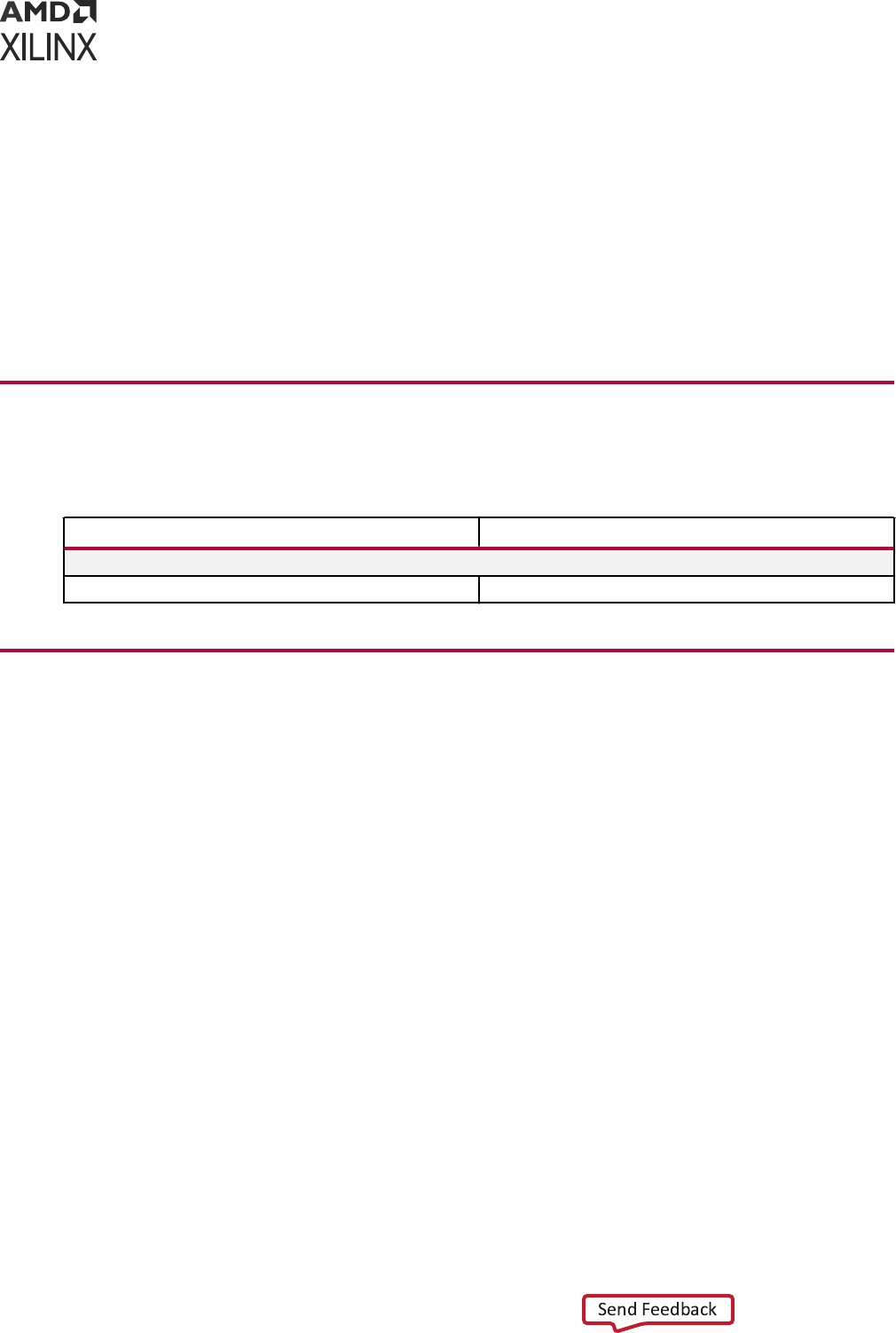
4. Designing FPGAs Using the Vivado Design Suite 4 Training Course
5. Vivado Design Suite QuickTake Video Tutorials
6. Vivado Design Suite QuickTake Video: Using the Vivado Timing Constraint Wizard
7. Vivado Design Suite QuickTake Video: Advanced Clock Constraints and Analysis
8. Vivado Design Suite QuickTake Video: Seng Input Delay
9. Vivado Design Suite QuickTake Video: Seng Output Delay
10. Vivado Design Suite QuickTake Video: Migrang UCF Constraints to XDC
Revision History
The following table shows the revision history for this document.
Section Revision Summary
06/01/2022 Version 2022.1
General Updates Editorial updates only. No technical content updates.
Please Read: Important Legal Notices
The informaon disclosed to you hereunder (the "Materials") is provided solely for the selecon
and use of Xilinx products. To the maximum extent permied by applicable law: (1) Materials are
made available "AS IS" and with all faults, Xilinx hereby DISCLAIMS ALL WARRANTIES AND
CONDITIONS, EXPRESS, IMPLIED, OR STATUTORY, INCLUDING BUT NOT LIMITED TO
WARRANTIES OF MERCHANTABILITY, NON-INFRINGEMENT, OR FITNESS FOR ANY
PARTICULAR PURPOSE; and (2) Xilinx shall not be liable (whether in contract or tort, including
negligence, or under any other theory of liability) for any loss or damage of any kind or nature
related to, arising under, or in connecon with, the Materials (including your use of the
Materials), including for any direct, indirect, special, incidental, or consequenal loss or damage
(including loss of data, prots, goodwill, or any type of loss or damage suered as a result of any
acon brought by a third party) even if such damage or loss was reasonably foreseeable or Xilinx
had been advised of the possibility of the same. Xilinx assumes no obligaon to correct any
errors contained in the Materials or to nofy you of updates to the Materials or to product
specicaons. You may not reproduce, modify, distribute, or publicly display the Materials
without prior wrien consent. Certain products are subject to the terms and condions of
Xilinx's limited warranty, please refer to Xilinx's Terms of Sale which can be viewed at hps://
Appendix B: Additional Resources and Legal Notices
UG903 (v2022.1) June 1, 2022 www.xilinx.com
Using Constraints 196

www.xilinx.com/legal.htm#tos; IP cores may be subject to warranty and support terms contained
in a license issued to you by Xilinx. Xilinx products are not designed or intended to be fail-safe or
for use in any applicaon requiring fail-safe performance; you assume sole risk and liability for
use of Xilinx products in such crical applicaons, please refer to Xilinx's Terms of Sale which can
be viewed at hps://www.xilinx.com/legal.htm#tos.
AUTOMOTIVE APPLICATIONS DISCLAIMER
AUTOMOTIVE PRODUCTS (IDENTIFIED AS "XA" IN THE PART NUMBER) ARE NOT
WARRANTED FOR USE IN THE DEPLOYMENT OF AIRBAGS OR FOR USE IN APPLICATIONS
THAT AFFECT CONTROL OF A VEHICLE ("SAFETY APPLICATION") UNLESS THERE IS A
SAFETY CONCEPT OR REDUNDANCY FEATURE CONSISTENT WITH THE ISO 26262
AUTOMOTIVE SAFETY STANDARD ("SAFETY DESIGN"). CUSTOMER SHALL, PRIOR TO USING
OR DISTRIBUTING ANY SYSTEMS THAT INCORPORATE PRODUCTS, THOROUGHLY TEST
SUCH SYSTEMS FOR SAFETY PURPOSES. USE OF PRODUCTS IN A SAFETY APPLICATION
WITHOUT A SAFETY DESIGN IS FULLY AT THE RISK OF CUSTOMER, SUBJECT ONLY TO
APPLICABLE LAWS AND REGULATIONS GOVERNING LIMITATIONS ON PRODUCT
LIABILITY.
Copyright
© Copyright 2012-2022 Xilinx, Inc. Xilinx, the Xilinx logo, Alveo, Arx, Kintex, Kria, Spartan,
Versal, Vis, Virtex, Vivado, Zynq, and other designated brands included herein are trademarks of
Xilinx in the United States and other countries. All other trademarks are the property of their
respecve owners.
Appendix B: Additional Resources and Legal Notices
UG903 (v2022.1) June 1, 2022 www.xilinx.com
Using Constraints 197
