
Instruction
Manual
Battery Backup
Sump Pump System
What to do
Terminals corroded or battery defective
Clean terminals or replace battery
Replace with 25 amp auto fuse
If fuse blows again, replace pump
Add distilled water to battery
Pump was activated
Check main pump for failure
Check circuit breaker & charging plug
If power is on, replace charger
Charger Operating
•
Warning
•
BATTERY
•
FUSE
•
WATER
•
PUMP
•
POWER
Push to
Test
System
Push to
Silence
Pump Alarm
Battery Operated
SUMP PUMP
TEST
RESET

Table of Contents
Important Safety Instructions
General . . . . . . . . . . . . . . . . . . . . . . .1
AC Power Requirements . . . . . . . . . .1
Personal Precautions . . . . . . . . . . . . .1
Preparing to Charge . . . . . . . . . . . . .1
DC Connection Precautions . . . . . . . .1
Introduction
Items Included in System . . . . . . . . .2
Additional Items Needed . . . . . . . . . .2
Pump & Pipe
Installation Instructions
Direct Discharge to Outside . . . . . .3,4
Hookup to Existing Discharge Pipe . .5,6
Battery Instructions
Preparation of the Battery . . . . . . . . .7
Control Unit Hookup
Positioning the Float Switch . . . . . . . .8
Installing the Battery Fluid Sensor . . .8
Hooking Up the Pump . . . . . . . . . . . .8
Hooking Up the Battery . . . . . . . . . . .8
Hooking Up the Charger . . . . . . . . . .8
Understanding the Warning
Lights and Alarms
Silencing the Alarm
During an Emergency . . . . . . . . . . . .9
Battery Alarm . . . . . . . . . . . . . . . . . .9
Cable or Terminal Problems . . . . .9, 10
Replacing the Battery . . . . . . . . . . .10
Fuse Alarm . . . . . . . . . . . . . . . . . . .10
Water Alarm . . . . . . . . . . . . . . . . . .10
Power Alarm . . . . . . . . . . . . . . . . . .11
Pump Alarm . . . . . . . . . . . . . . . . . .11
Replacing the Pump . . . . . . . . . . . .11
Charger Operating . . . . . . . . . . . . . .11
Test Button . . . . . . . . . . . . . . . . . . .11
Testing the Float Switch . . . . . . . . . .11
Parts & Service Information
Technical Support . . . . . . . . . . . . . .11
Important
Safety Instructions
General
Do not expose the control unit to rain or
snow.
Pull the plug rather than the cord when
disconnecting the control unit.
An extension cord should not be used
unless absolutely necessary.
To reduce the risk of electric shock,
unplug the control unit and disconnect
the cables from the battery before
attempting any maintenance or cleaning.
Do not disassemble the control unit.
When service is required, contact
Glentronics technical support at (800)
991-0466, option 3.
AC Power Requirements
The control unit must receive 115 volts
AC +/- 5% from the AC outlet. Any
voltage lower than this will cause the
power failure alarm to activate. Lower
voltages can be caused by utility
company brown outs or heavy power
draw from other appliances on the same
circuit.
Personal Precautions
Wear eye protection and avoid touch-
ing your eyes while working near the
battery.
If battery acid contacts skin or clothing,
wash immediately with soap and water.
If acid enters eye, immediately flood eye
with running cold water for at least 10
minutes and get medical attention.
Never smoke or allow a spark or flame
in the vicinity of the battery.
Remove personal metal items such as
rings, bracelets, watches, etc. when
working with a lead-acid battery.
Preparing to Charge
Charge only LEAD-ACID batteries with
the Basement Watchdog Special control
unit. Do not use the control unit for
charging dry-cell batteries that are most
commonly used with home appliances.
Be sure the area around the battery is
well-ventilated.
When cleaning or adding water to the
battery, gas can be forcefully blown
away from the top of the battery by using
a piece of cardboard or other
non-
metallic material as a fan.
Clean the battery terminals. Be careful
to keep corrosion from coming in con-
tact with your eyes.
DC Connection Precautions
Connect and disconnect the battery
cable rings only after removing the
charger from the electric outlet. Never
allow the rings to touch each other.
Coat the terminals with a thin coat of
petroleum jelly to retard corrosion.
Attach the rings on the ends of the
battery cables to the battery posts and
secure them with wing nuts to insure a
good connection.
Follow these steps when the battery is
installed. A spark near the battery may
cause a battery explosion. To reduce
the risk of a spark near the battery:
Check the polarity of the battery posts.
The POSITIVE (+) battery post usually
has a larger diameter than the NEG-
ATIVE (-) post.
Connect the large ring on the POSITIVE
(RED) wire from the control unit to the
POSITIVE (+) post of the battery.
Connect the small ring on the NEG-
ATIVE (BLACK) wire from the control
unit to the NEGATIVE (-) post of the
battery.
When disconnecting the control unit,
first disconnect the charger, and then
remove the rings from the battery
terminals.
Page 1
POSITIVE
POST HAS
LARGER
DIAMETER
NEGATIVE
POST HAS
SMALLER
DIAMETER
Introduction
The Basement Watchdog Special
backup sump pump system is battery-
operated. It is designed as an emer-
gency backup system to support your
regular AC sump pump, and it will
automatically begin pumping if your
main AC pump fails. Should any mal-
function or emergency occur that
involves the sump pump, the battery,
or the AC power, your Basement
Watchdog system will sound an alarm
and indicate the nature of the problem
and the solutions by means of a lighted
display on the control panel.
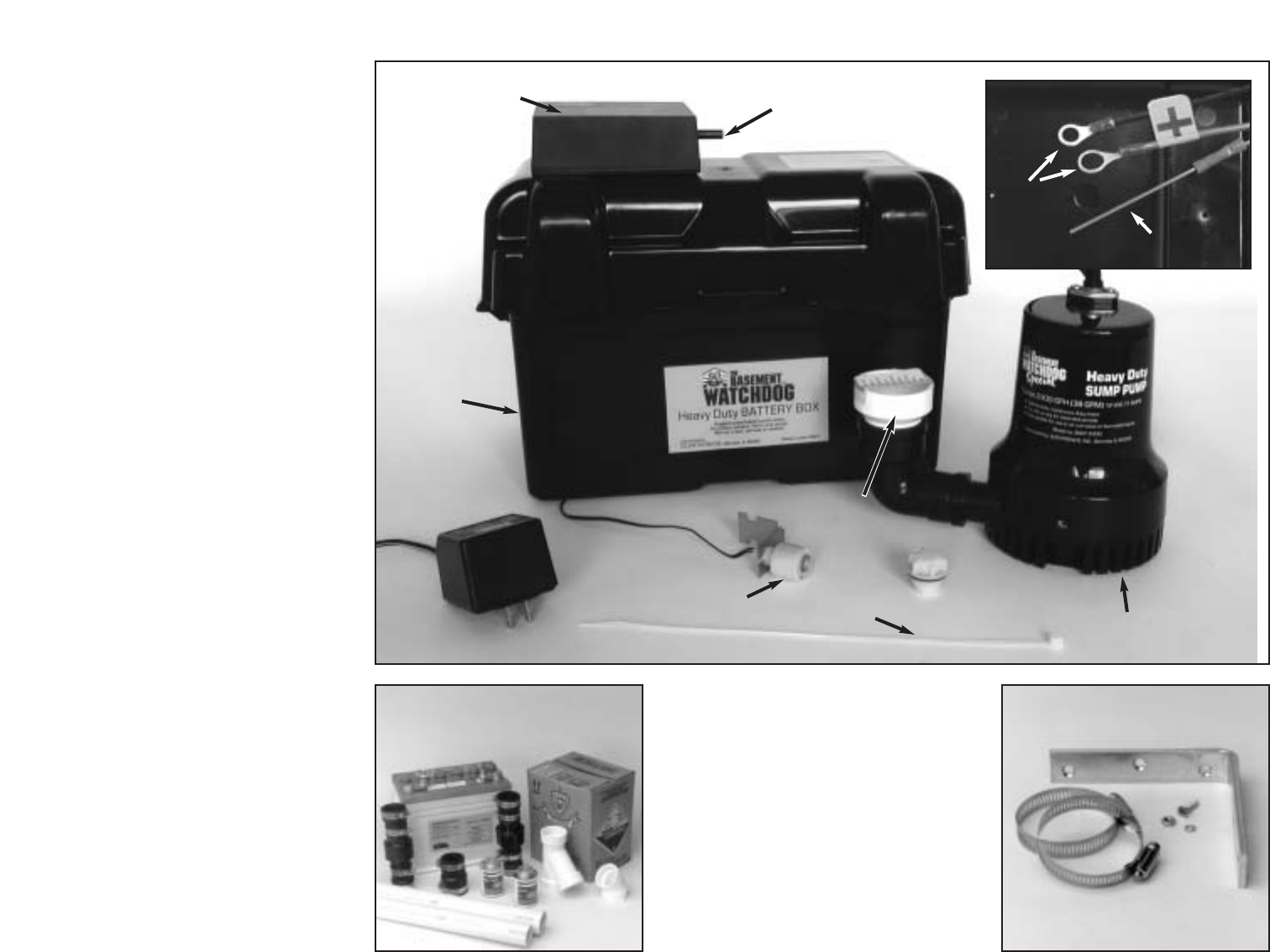
The Basement Watchdog sump
pump system includes:
A control unit with a float switch
and a battery fluid level sensor
A pump with 1
1
/2" PVC pipe
adapter
A plastic wire tie for mounting the
float switch
A battery box with safety strap
A battery cap with a hole to
accommodate the fluid sensor
A battery charger
A 20 amp fuse
A plug to silence the POWER alarm
You will also need to supply:
A Basement Watchdog 7.5 Hour
Battery, or another deep cycle
battery (
Do not use a main-
tenance-free or a sealed battery.
)
1
1
/2" PVC pipe and fittings
PVC cement and primer
A rubber union with hose clamps
or a "Y" connector and two (2)
check valves depending on the
installation method you use
Six (6) quarts of 1.265 specific
gravity battery acid
For narrow sump pits you will need
some additional parts:
An "L" bracket at least 6 inches
long. (Preferably one that will not
rust.)
Two (2) stainless steel hose
clamps
One (1) stainless steel screw
(#8-32 x
3
/
4
"), a matching washer
& nut
Page 2
BATTERY WIRES
CONTROL UNIT
SILENCE
PLUG
BATTERY
BOX
CHARGER
CAP
WIRE TIE
FLOAT
SWITCH
PIPE
ADAPTER
PUMP
FLUID SENSOR
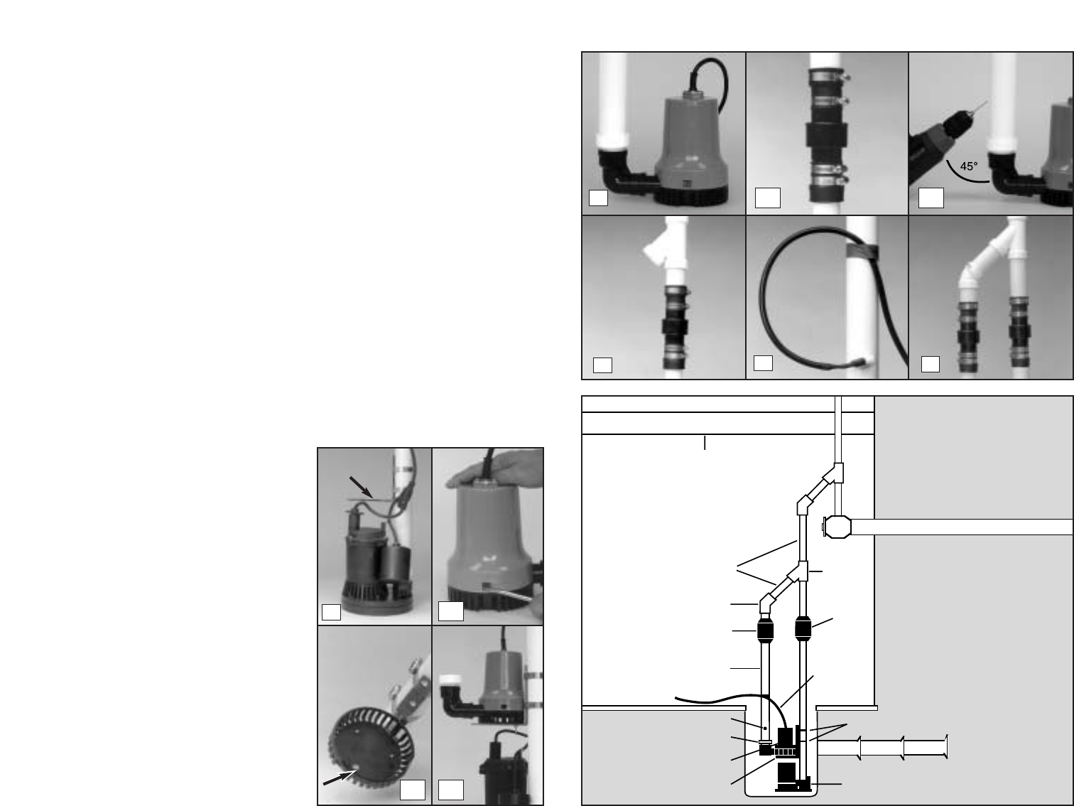
Pump & Pipe
Installation Instructions
(Direct Discharge to Outside)
There are two basic methods that can
be used to install the pump, (A) a direct
discharge to the outside of the building,
or (B) a hookup to an existing discharge
pipe.
Whenever possible, install your Base-
ment Watchdog Special system with a
direct discharge to the outdoors. By
using this method, there will always be
an outlet for the water from the sump.
During times of very heavy rain, many
storm sewers fill up. If your pump is
trying to discharge water into a full
sewer, there is nowhere for the water to
go. This defeats the purpose of the
backup system. By discharging directly
outdoors, there is always an outlet for
the water that is pumped out of the
sump.
There are two options for installing your
sump pump with a direct discharge to
the outside. If you have a sump pit wide
enough to place the backup pump next
to the main pump, use Method A. If your
sump pit is too narrow, the pump may be
mounted above the main pump. In this
instance use the instructions for Method
Aa.
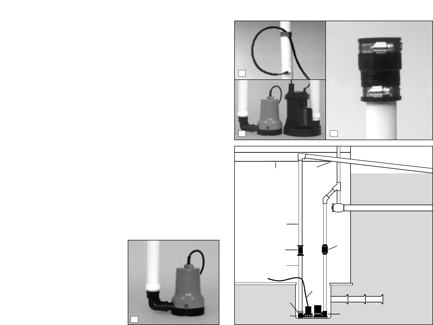
METHOD A: DIRECT DISCHARGE
TO THE OUTSIDE OF THE
BUILDING (Diagram A)
1. Cut a four-foot (4’) piece of 1
1
/2"
rigid PVC pipe and cement it to the
threaded fitting that is attached to
the elbow on the pump.
2. Secure the pump wire so that the
plug on the end will not fall into the
sump. Attach the wire to the pipe
with a piece of tape.
3. Place the pump with the 4’ PVC
pipe attachment on the bottom of
the sump floor next to the main AC
pump.
Do not mount the pump to
any existing pipes...it should be
placed on the floor of the sump.
A
brick may be placed under the
pump if there are rocks or other
debris on the sump floor.
4. Attach a rubber union (sold sep-
arately) to the top of the 1
1
/2" pipe.
This will allow the pump to be
removed easily, should the need
arise.
The path of the rest of the pipe and the
details of each installation will vary.
Using sound plumbing practices try to
route the discharge pipe to an exterior
wall via the shortest path with the few-
est turns. The pipe section exiting the
building should be on a downward slope
so that the water in the pipe will exit
outside rather than return to the sump.
Extend the discharge pipe outside the
building as far as possible to avoid the
return of discharged water to the sump.
Be sure to seal the hole in the wall
where the pipe exits and cement or
clamp all connections securely to
prevent leaking.
No check valve is
needed with this method of installation,
as long as you use less than 20 feet of
pipe.
Page 3
PUMP
WIRE
PIPE ADAPTER
BASEMENT WATCHDOG
PUMP
FLOOR
JOIST
MAIN AC PUMP
SLOPE
PIPE
DOWN
RIGID
1-1/2"
PVC PIPE
RIGID
1-1/2"
PVC PIPE
RUBBER
UNION
CHECK
VALVE
DRAIN TILE
1
2
3 4
Diagram A
Pump & Pipe
Installation Instructions
(Direct Discharge to Outside)
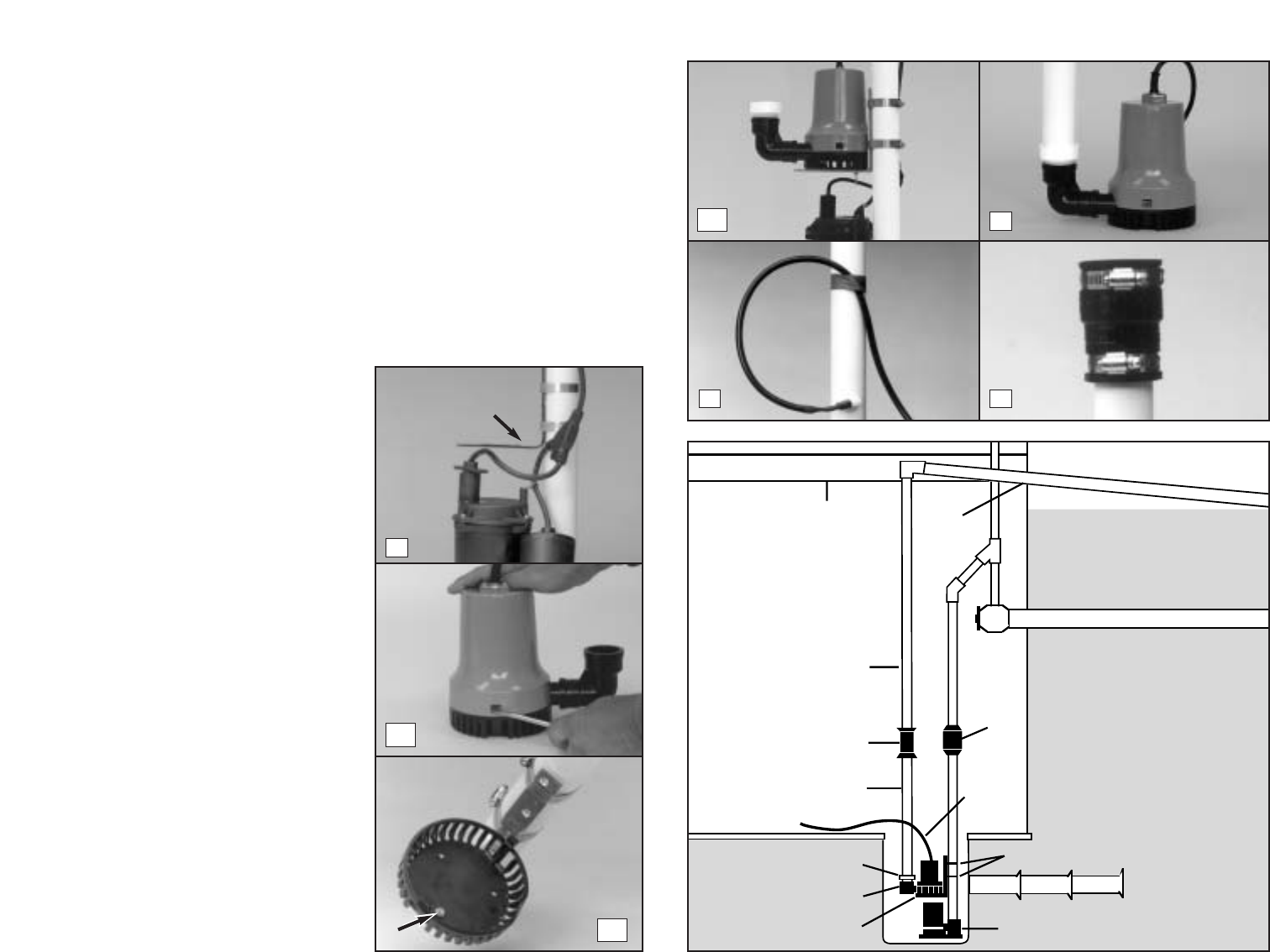
METHOD Aa: DIRECT DISCHARGE
TO THE OUTSIDE OF THE
BUILDING FOR NARROW
SUMP PITS (Diagram Aa)
1. Attach an "L" bracket to the dis-
charge pipe of the main AC pump
with two (2) stainless steel hose
clamps. Position the bracket so the
bottom of the "L" is just above the
top of the main pump, and out of the
way of any float switch on the main
pump.
2. (a) Remove the black bottom
strainer of the pump by pressing in
the two tabs on the strainer. There
are holes suitable for mounting on
the bottom of the strainer. (b) Us-
ing a #8-32x
3
/4" stainless screw,
washer & nut, attach the strainer to
the "L" bracket. (c) Once the
strainer is attached, simply press
the pump body onto the mounted
strainer.
3. Cut a three-foot (3’) piece of 1
1
/2"
rigid PVC pipe and cement it to the
threaded fitting that is attached to
the elbow on the pump.
4. Secure the pump wire so that the
plug on the end will not fall into the
sump. Attach the wire to the pipe
with a piece of tape.
5. Attach a rubber union (sold sep-
arately) to the top of the 1
1
/2" pipe.
This will allow the pump to be
removed easily, should the need
arise.
The path of the rest of the pipe and the
details of each installation will vary.
Using sound plumbing practices try to
route the discharge pipe to an exterior
wall via the shortest path with the fewest
turns. The pipe section exiting the
building should be on a downward slope
so that the water in the pipe will exit
outside rather than return to the sump.
Extend the discharge pipe outside the
building as far as possible to avoid the
return of discharged water to the sump.
Be sure to seal the hole in the wall where
the pipe exits and cement or clamp all
connections securely to prevent leaking.
No check valve is needed with this
method of installation, as long as you
use
less than 20 feet of pipe.
Page 4
PUMP
WIRE
HOSE CLAMPS
PIPE ADAPTER
BASEMENT WATCHDOG
PUMP
"L" BRACKET
FLOOR
JOIST
MAIN AC PUMP
SLOPE
PIPE
DOWN
RIGID
1-1/2"
PVC PIPE
RUBBER
UNION
CHECK
VALVE
RIGID
1-1/2"
PVC PIPE
DRAIN TILE
1
2a
2c
2b
3
4 5
Diagram Aa
“L” BRACKET
Pump & Pipe
Installation Instructions
(Hookup to Existing Discharge Pipe)
If the direct discharge method (Method
A) is not possible, the Basement
Watchdog Special backup system can
be hooked up to the same pipe as your
AC sump pump by installing a "Y"
connector and two check valves.
Check your local plumbing codes. Some
municipalities prohibit the discharge of
sump water into the sewer system.
If you have a sump pit wide enough to
place the backup pump next to the main
pump, use Method B. If your sump pit is
too narrow, the pump may be mounted
above the main pump. In this instance
use the instructions for Method Bb.
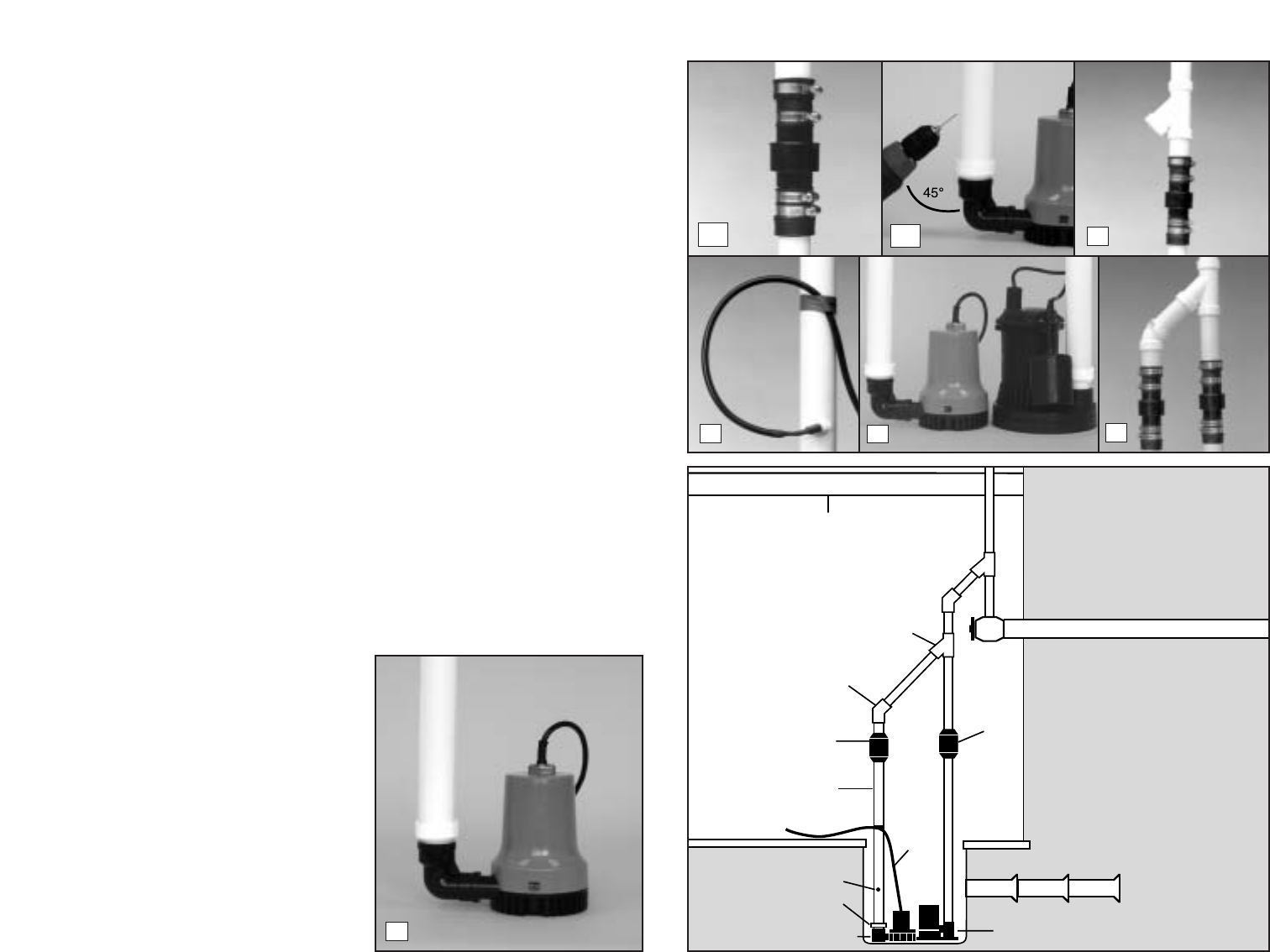
METHOD B: HOOKUP TO AN
EXISTING DISCHARGE PIPE
(Diagram B)
1. Cut a four-foot (4’) piece of 1
1
/
2
"
rigid PVC pipe and cement it to the
threaded fitting that is attached to
the elbow on the pump.
2. (a) Install a check valve on the PVC
pipe attached to the Basement
Watchdog pump. (b) IMPORTANT:
WHEN A CHECK VALVE IS USED,
DRILL A
1
/8" HOLE IN THE 1
1
/2"
PVC PIPE THREE INCHES (3")
ABOVE THE CONNECTION TO
THE BASEMENT WATCHDOG
SPECIAL PUMP. Drill the hole at a
45˚ angle toward the bottom of the
sump to avoid splashing water
outside the sump pit. If a 1/8" hole
is not drilled above the pump, an air
lock may prevent the pump from
pumping.
3. If there is no check valve on the
pipe of the main AC pump, one
must be installed at this time. Then
install a "Y" connector above the
check valve on the discharge pipe
for the main AC pump.
4. Secure the pump wire so that the
plug on the end will not fall into the
sump. Attach the wire to the pipe
with a piece of tape.
5. Place the pump with the 4’ PVC
pipe attachment on the bottom of
the sump floor, next to the main AC
pump.
Do not mount the pump to
any existing pipes...it should be
placed on the floor of the sump.
A
brick may be placed under the
pump if there are rocks or other
debris on the sump floor.
6. Connect a 1
1
/2" diameter discharge
pipe above the check valve of the
Basement Watchdog pump, and
attach a 45˚ elbow to that pipe.
Extend another piece of pipe to
reach the "Y" connector you have
inserted above the check valve on
the discharge pipe of the main pump.
7. Cement or clamp all connections
securely to prevent leaking.
Page 5
PUMP
WIRE
PIPE ADAPTER
BASEMENT WATCHDOG
PUMP
FLOOR
JOIST
MAIN AC PUMP
RIGID
1-1/2"
PVC PIPE
CHECK
VALVE
DRAIN TILE
1/8" HOLE
45° ELBOW
"Y" CONNECTOR
CHECK
VALVE
3
4
5
6
1
2a
2b
Diagram B
Pump & Pipe
Installation Instructions
(Hookup to Existing Discharge Pipe)
METHOD Bb: HOOKUP TO AN
EXISTING DISCHARGE PIPE FOR
NARROW SUMP PITS
(Diagram Bb)
1. Attach an "L" bracket to the dis-
charge pipe of the main AC pump
with two (2) stainless steel hose
clamps. Position the bracket so the
bottom of the "L" is just above the
top of the main pump, and out of the
way of any float switch on the main
pump.
2. (a) Remove the black bottom
strainer of the pump by pressing in
the two tabs on the strainer. There
are holes suitable for mounting on
the bottom of the strainer. (b) Using
a #8-32x
3
/
4
" stainless screw,
washer and nut, attach the strainer
to the "L" bracket. (c) Once the
strainer is attached, simply press
the pump body onto the mounted
strainer.
3. Cut a three-foot (3’) piece of 1
1
/
2
"
rigid PVC pipe and cement it to the
threaded fitting that is attached to
the elbow on the pump.
4. (a) Install a check valve on the PVC
pipe attached to the Basement
Watchdog pump. (b) IMPORTANT:
WHEN A CHECK VALVE IS USED,
DRILL A
1
/
8
" HOLE IN THE 1
1
/
2
"
PVC PIPE THREE INCHES (3")
ABOVE THE CONNECTION TO
THE BASEMENT WATCHDOG
PUMP. Drill the hole at a 45˚ angle
toward the bottom of the sump to
avoid splashing water outside the
sump pit. If a 1/8" hole is not drilled
above the pump, an air lock may
prevent the pump from pumping.
5. If there is no check valve on the
pipe of the main AC pump, one
must be installed at this time. Then
install a "Y" connector above the
check valve on the discharge pipe
for the main AC pump.
6. Secure the pump wire so that the
plug on the end will not fall into the
sump. Attach the wire to the pipe
with tape.
7. Connect a 1
1
/
2
" diameter discharge
pipe above the check valve of the
Basement Watchdog pump, and
attach a 45˚ elbow to that pipe.
Extend another piece of pipe to
reach the "Y" connector you have
inserted above the check valve on
the discharge pipe of the main pump.
8. Cement or clamp all connections
securely to prevent leaking.
Page 6
PUMP
WIRE
HOSE CLAMPS
PIPE ADAPTER
BASEMENT WATCHDOG
PUMP
"L" BRACKET
FLOOR
JOIST
MAIN AC PUMP
RIGID
1-1/2"
PVC PIPE
CHECK
VALVE
RIGID
1-1/2"
PVC PIPE
DRAIN TILE
45° ELBOW
"Y" CONNECTOR
CHECK
VALVE
1/8" HOLE
3
5
1
6
7
4a 4b
2a
2b
2c
Diagram Bb
“L”
BRACKET
Battery
Instructions
The Basement Watchdog 7.5 Hour
Standby Battery has been designed to run
this system for a minimum of 7.5 hours of
continuous pumping. However, most of the
time the pump will turn on and off, and the
battery will run the pump intermittently for
days. In addition, the unique materials in
the battery enable it to last for five to seven
years in standby service.
The use of automotive batteries is
not
recommended. Automotive batteries are
not designed for this application. They will
only run the pump for a short time and will
have a shorter life than a standby battery.
Do not use a maintenance-free or sealed
battery. They are made of different
materials and will trigger a false "Battery
problem" alarm.
In addition, the battery fluid sensor and
cap are designed to fit the Basement
Watchdog batteries.
(As a safety pre-
caution, do not use the cap on batteries of
a different brand, and do not drill a hole in
the cap of another brand of battery to
accommodate the fluid sensor.)
PREPARING THE
BASEMENT WATCHDOG
STANDBY BATTERY
The Basement Watchdog 7.5 Hour
Standby Battery is shipped dry (without
acid) so it never loses power before you
take it home. A battery is activated when
the acid is added, and then it slowly begins
to deteriorate as it ages. By adding the
acid just before use, the battery will always
be fresh. Use 1.265 specific gravity
battery acid to fill the battery. It is available
where you purchased the battery.
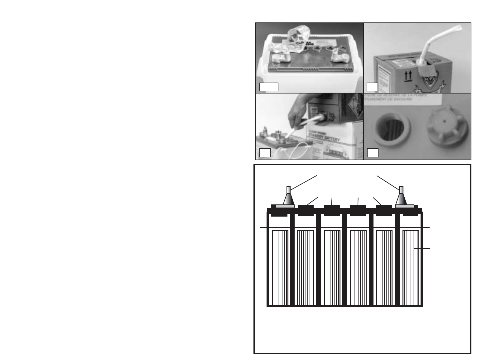
IMPORTANT: REVIEW THE
SAFETY INSTRUCTIONS
BEFORE YOU PROCEED
1. Place the battery box on the floor.
Position the battery box safety strap
under the box and through the loop on
the top of the battery box.
2. Place the dry (unfilled) battery into the
battery box. Remove the foil seal on the
top of the battery.
3. (a) Carefully push in the perforated tab
at the top of the acid pack. Pull up the
large tab and pull out the dispensing
hose. Hold the hose upright above the
pack and squeeze the hose forcing all
the acid back into the pack. Cut off the
tip of the hose. (b) Position the acid
pack and battery as shown in picture 3b.
Insert the end of the hose into each cell.
Control the flow by pinching the hose
with thumb and forefinger.
Fill each cell
of the battery to a level just covering the
battery plates, and then go back and top
off each cell equally. It is important to
have the cells filled equally
. (c) The acid
should reach a level just below the cap
ring. (Diagram C)
A newly filled battery will sometimes
require additional acid after about ten
minutes. Re-examine the fill level and
add additional acid, if necessary. The
battery acid may bubble at this time and
give off a sulfur-like smell, but this is
normal. After the battery has been filled,
screw the caps on the top of the battery.
Always be careful and avoid contact with
skin, clothing, furniture or floor.
When you fill the battery for the first time,
it will be the only time you add acid to the
battery. When the fluid level is low, add
distilled water to the cells. Never add more
acid.
Page 7
2nd LEVEL
1st LEVEL
PLATES
CELL WALL
1. FILL TO 1st LEVEL, COVER THE PLATES
2. THEN FILL TO 2nd LEVEL, JUST BELOW
THE BOTTOM OF THE CAP RINGS
BATTERY TERMINALS
BATTERY CAP RINGS
CROSS SECTION OF BATTERY
Diagram C
1 & 2
3a
3b 3c
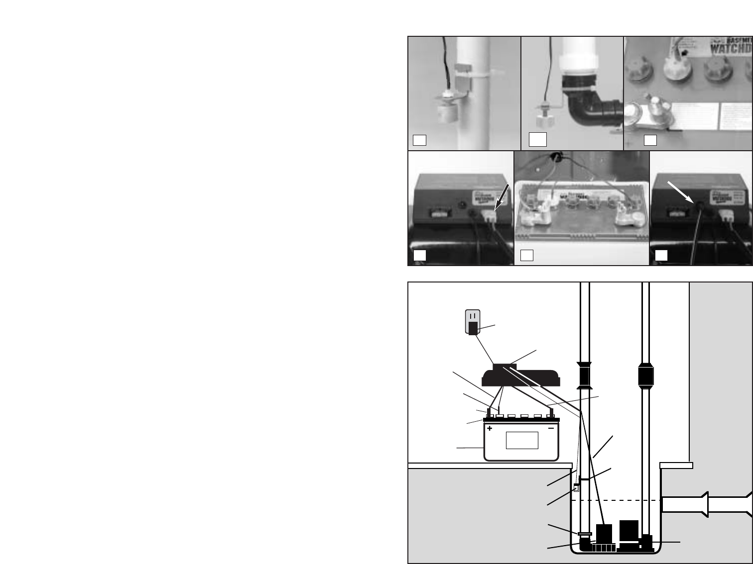
Control Unit Hookup
When you position the control unit, be
sure the charger cord will reach the AC
power outlet and the pump cable and
the float switch will reach the bottom of
the sump. Position the unit in a well-
ventilated area. (Diagram D)
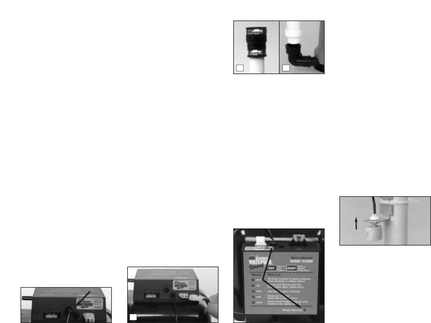
1.
Positioning the float switch: The
float switch will turn on the pump
when the water rises to the top of
the switch, and it will remain
running as long as the water is
above the float switch. When the
water drops below the float switch
an internal timer in the control unit
will keep the pump running an
additional 30-40 seconds to empty
the sump pit. The switch should be
mounted six inches (6") above the
activation level of the main AC
pump. Attach the float switch very
securely to the discharge pipe of
the backup pump with the plastic
wire tie. (If you are stacking the
pumps in a narrow sump pit, the
float may be attached to the elbow
of the backup pump.)
Be sure the
switch is positioned vertically with
the mounting bracket at the top. Do
not tilt the switch. Do not position
the float switch on the side of the
discharge pipe facing the drain tile
or any incoming rush of water! Do
not position it next to the power
cord of the AC pump.
2. Installing the battery fluid
sensor: Replace the battery cap
that is 2nd from the POSITIVE (+)
post of the battery with the battery
cap that is provided in the
Basement Watchdog sump pump
package. An arrow on the top of the
battery marks this position. There
are two holes in the sensor cap.
Insert the fluid sensor in the hole
that is off-center on the top of the
cap.
Do not glue the sensor into the
cap. If you are not using the
Basement Watchdog battery, you
cannot use the battery fluid sensor,
however you must attach the
sensor to the POSITIVE (+) post of
the battery or the alarm will sound
continuously.
The Basement
Watchdog Special sump pump
system will not warn you if the fluid
level is low in this configuration. You
will need to check your battery
every couple of months to see if it
needs water.
3. Hooking up the pump: Plug the
pump wires into the pump connect-
or on the back of the control unit.
4.
Hooking up the battery: Remove
the wing nuts. Coat the terminals
with a little petroleum jelly to
prevent corrosion. Attach the
battery cables to the battery...the
RED wire to the POSITIVE (+) post,
the BLACK wire to the NEGATIVE
(-) post. Tighten the wing nuts.
5.
Hooking up the charger: Immed-
iately plug the charger into the
charger hole on the back of the
control unit and into an AC outlet on
the wall.
6. If the pump alarm is sounding,
press the reset button to silence the
alarm.
7. Put the cover on the battery box,
and secure it with the safety strap.
The Basement Watchdog Special
Battery Backup Sump Pump System
is ready to use!
Page 8
CHARGER
BATTERY
BOX
PUMP
WIRE
DRAIN TILE
MAIN AC PUMP
FLOAT WIRE
FLOAT SWITCH
PIPE ADAPTER
BASEMENT WATCHDOG
PUMP
WIRE
TIE
BLACK
BATTERY
CABLE
BATTERY
TERMINAL
WALL OUTLET
RED
BATTERY
CABLE
SENSOR
CONTROL
UNIT
1
3
2
54
1a
Diagram D
20 AMP FUSE
CHARGER
PUMP
20 AMP FUSE
CHARGER
PUMP
Understanding the
Warnings & Alarms
The Basement Watchdog Special con-
trol unit features a series of warning
lights that pinpoint potential problems.
In addition, an alarm sounds to alert you
to the problem. In some cases, the
lights and alarm will go off automatically
when the problem has been solved. In
others, the RESET button must be
pushed to silence the alarm. Refer to
the table below for a quick review of the
features and their corresponding alarm
status.
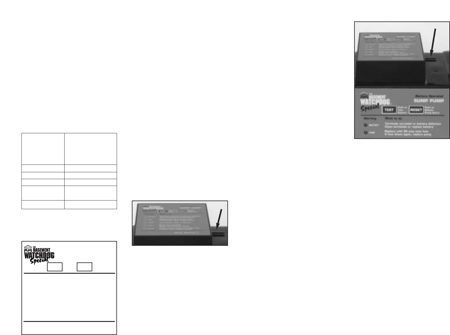
SILENCING THE ALARM
DURING AN EMERGENCY
Your Basement Watchdog Special sump
pump system is equipped with a plug that
allows you to silence the POWER and
PUMP alarms during an emergency or
power failure. The plug is located in a
bag attached to the charger cord. To
silence the alarm, insert the plug into the
jack on the right side of the control unit.
The plug must be removed and the alarm
should be reactivated when the emer-
gency is over, or when the power is
restored. This plug does not effect the
BATTERY, FUSE, and WATER alarms.
To reactivate the alarm, remove the plug
and place it back in the bag on the
charger cord. If your pump was activated
during the power outage, the PUMP
alarm will still be sounding. Press the
RESET button to silence that alarm.
If you do not remove the plug, you will
not be warned the next time a POWER
or PUMP emergency arises.
BATTERY ALARM
This light and alarm will go on when the
control unit senses that the battery has
approximately
1
/
2
hour of pumping
energy left. This could occur when the
pump has been running for many hours
and is reaching the last half-hour of
operating power, or it could occur
because the battery is getting old and
should be replaced.
The alarm can also be triggered by
corrosion of the battery cable and the
battery terminals. Clean and tighten the
battery terminals as described at the
right. If this warning goes on while the
pump is running, you will have a minimum
of
1
/2 hour to replace the battery. (In most
cases, the pump does not run contin-
uously, and therefore, you actually have
much longer.) In a severe emergency, if a
replacement battery is not available, you
could temporarily use your car battery.
Once the AC power is restored, the
battery will recharge, unless it is old or
damaged. The alarm will go off when the
AC power is restored and the pumping
energy reaches
1
/2 hour or more.
In the event that your Basement
Watchdog Special sump pump system
has been called on to pump for
extended periods of time, the battery
can become very depleted. In this
condition, when the AC power is
returned to the unit, a BATTERY alarm
will continue to sound. The battery may
need a longer period to recharge.
For a fast recharge, an automotive or
marine battery charger can be used to
recharge the battery.
When another
charger is used, first disconnect the
controller from the battery.
To silence the alarm while the battery is
recharging, do the following:
1. Insert the plug into the jack on the
right side of the control unit.
2. Press the TEST button, but not the
RESET button.
3. Leave the system in this condition
for 24 hours.
4. After a 24-hour charging period,
remove the plug and press the
RESET button.
5. If the battery is recharged, all
alarms will be off.
6.
If the alarm is still sounding, the
battery is defective or the posts are
corroded. Clean the terminals. If the
alarm still sounds, replace the battery.
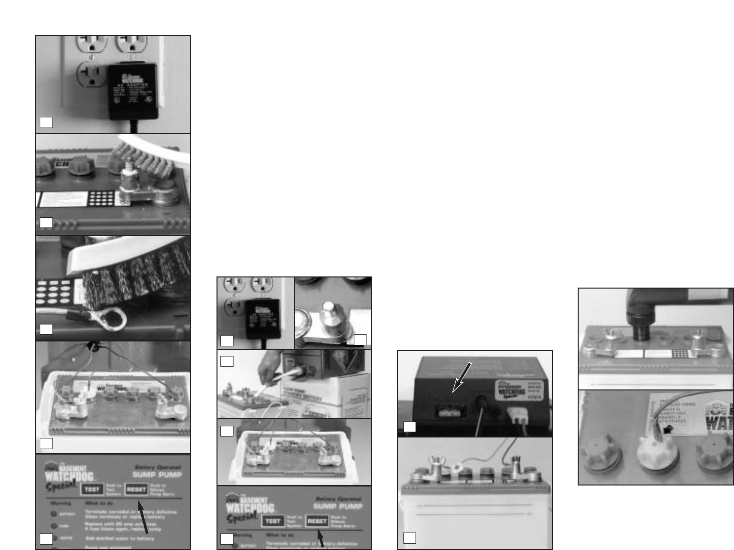
TO CHECK FOR CABLE OR
TERMINAL PROBLEMS
IMPORTANT: REVIEW THE
SAFETY INSTRUCTIONS
BEFORE YOU PROCEED
1. Unplug the charger from the wall
outlet.
2. Remove the battery cables and
clean the battery posts with a bat-
tery post terminal cleaner or a wire
brush and a 50/50 solution of water
and baking soda. Do not allow the
soda water to enter the battery.
Thoroughly dry the posts and apply a
thin coat of petroleum jelly or another
terminal protective material.
3. Clean the corrosion off of the con-
nectors on the end of the battery
wires. Use a stiff brush or sand-
paper.
4. Replace the battery cables, RED to
the POSITIVE (+) post, and BLACK
to the NEGATIVE (-) post.
5. Plug the charger into the wall outlet.
6. You may have to press the RESET
button to silence the pumping alarm.
Page 9
Warning
BATTERY
FUSE
WATER
PUMP
POWER
Alarm shuts off
automatically
when problem
is corrected
Yes
Yes
Yes
No, must push
"RESET" button
Yes
FRONT PANEL OF CONTROL UNIT
What to do
Terminals corroded or battery defective
Clean terminals or replace battery
Replace with 25 amp auto fuse
If fuse blows again, replace pump
Add distilled water to battery
Pump was activated
Check main pump for failure
Check circuit breaker & charging plug
If power is on, replace charger
Charger Operating
•
Warning
•
BATTERY
•
FUSE
•
WATER
•
PUMP
•
POWER
Push to
Test
System
Push to
Silence
Pump Alarm
Battery Operated
SUMP PUMP
TEST
RESET
REPLACING THE BATTERY
IMPORTANT: REVIEW THE
SAFETY INSTRUCTIONS
BEFORE YOU PROCEED.
1. Unplug the charger from the wall.
2. Remove the battery cables from the
battery posts.
3. Fill the battery following the in-
structions on page 7.
4. Coat the battery terminals with a
little petroleum jelly and replace the
battery cables, RED to the
POSITIVE (+) post and BLACK to
the NEGATIVE (-) post. Replace
the battery cap in the cell which is
2nd from the POSITIVE post with
the yellow cap from the old battery.
Insert the fluid sensor in the cap.
5. Plug the charger into the wall outlet.
6. You may have to press the reset
button to silence the pumping alarm.
FUSE
This alarm indicates that the 20-amp
safety fuse on the back of the control
unit has blown. This can be the result of
a clogged pump motor, or pump wires
that have been shorted out. To correct
the problem:
1. Unplug the charger from the wall
and remove the cables from the
battery.
2. Check the pump for debris and
remove it if any is found.
3. Check the pump wires. Make sure
there are no exposed wires touch-
ing. Insulate any exposures with
electrical tape.
4. Replace the 20-amp fuse on the
back of the unit.
5. Reconnect the battery cables to the
battery the RED cable to the
POSITIVE (+) post, the BLACK
cable to the NEGATIVE (-) post.
6. Plug the charger into the wall.
7. Press the test button. If the fuse
blows again, replace the pump.
WATER ALARM
If this warning light and alarm are on,
you need to add distilled water to the
battery.
IMPORTANT; REVIEW THE
SAFETY INSTRUCTIONS
BEFORE YOU PROCEED
Remove the top of the battery box.
Unscrew the six battery caps. Add
distilled water to each cell. If distilled
water is not available; tap water with a
low mineral content may be used. Well
water is not recommended.
Never add
more acid. Fill the battery to the 2nd level
as shown in Diagram C on page 7.
Replace the caps and the fluid sensor.
Be sure the fluid sensor is positioned in
the 2nd cell from the positive post. It’s
marked with an arrow on the top of the
battery. The warning light will turn off
automatically when the battery is refilled.
Page 10
1
2
3
4
6 6
4
1
2
4
5
3
20 AMP FUSE
CHARGER
PUMP
POWER ALARM
There are several causes for power
failure. The most common is a power
outage by your electric company. During
this emergency, the Basement Watchdog
Special system will automatically switch
to battery power and protect your base-
ment from flooding. You can silence the
POWER alarm temporarily by inserting
the plug into the silence jack on the side
of the control box (see page 9). The light
and the alarm will both turn off.
The Basement Watchdog Sump Pump
System will continue to operate and
pump while the alarm is silenced. This
plug also silences the PUMP alarm.
If the power is on in the rest of the house,
check the home circuit breaker or fuse
box for failure, and correct the problem.
Check the charger. Make sure it is
securely plugged into the wall outlet.
Check the charger plug that fits into the
rear panel of the control unit. Make sure
it is securely plugged into the control unit.
The control unit must receive 115 volts
AC +/- 5% from the AC outlet. Any
voltage lower than this will cause the
power failure alarm to activate. Lower
voltages can be caused by utility
company brown outs or heavy power
draw from other appliances on the same
circuit.
If all the connections are secure and the
wall outlet is operating, but the POWER
warning light is still lit, replace the
charger unit with a Basement Watchdog
1.6 amp charger. Contact Glentronics,
Inc. at (800) 991-0466, option 3.
PUMP ALARM
The PUMP warning stays on to alert you
to the fact that the standby system was
used to empty water from the sump. Try
to determine what caused the system to
operate. Check the main pump for
failure. Another possibility is that the
power was out while you were away
and the backup system automatically
pumped the water out of the sump. Or,
if the incoming water was more than
your AC sump pump could handle,
then the backup system automatically
pumped the water out of the sump. It is
also possible that your check valve is
stuck and needs to be replaced.
After determining the source of the
problem, push the RESET button to
silence the alarm.
REPLACING THE PUMP
1. Unplug the charger and the pump
from the back of the control unit.
2. Release the rubber union or check
valve and remove the pump and the
rigid PVC pipe section from the
sump.
3. Unscrew the pipe and fitting from
the old pump and screw them into
the new pump.
4. Lower the pump into the sump and
reconnect the rubber union or
check valve.
5. Plug the pump wires and charger
into the back of the control panel.
CHARGER OPERATING
This green light should always be lit. It
indicates that the charger is operating
and that all connections are intact. If for
any reason the AC power is interrupted,
or a plug comes loose, this light will go
off, the red POWER light will appear,
and an alarm will sound.
Check the charger. Make sure it is
securely plugged into the wall outlet.
Check the charger plug that fits into the
rear panel of the control unit. Make sure
it is securely plugged into the control unit.
If all connections are secure and the
wall outlet is operating, but the POWER
warning light is still flashing, replace the
charger unit with a Basement Watchdog
1.6 amp charger from Glentronics, Inc.
TEST BUTTON
The TEST button may be used to check
the pump and system. Push the TEST
button. This will activate the pump for as
long as you hold the button, and it will
activate the pumping cycle for 30-40
seconds after you release it.
TESTING THE FLOAT SWITCH
Manually testing the float switch
periodically is highly recommended.
Lift the float up and let go. This will
activate the pump. The controller will
run the pump for approximately 40
seconds so it can empty all the water in
the sump pit. If there is no water in the
sump, the pump can run dry for this
amount of time. The alarm will sound
and the pump light will go on. After the
pump has stopped, push the RESET
button to silence the alarm. If the
RESET button is pressed before the
pump has stopped, the alarm will go off
temporarily. Wait for the pump to stop
pumping, then push the RESET button
to completely silence the alarm.
PARTS & SERVICE INFORMATION
You can receive technical support, parts
or service information by calling
Glentronics, Inc. at (800) 991-0466,
option 3. Send your unit to the following
address for repairs:
Glentronics, Inc.
640 Heathrow Dr.
Lincolnshire, IL 60069
Page 11
2
1
3
©2001, Glentronics, Inc. 1806001
LIFT
FLOAT
20 AMP FUSE
CHARGER
PUMP
20 AMP FUSE
CHARGER
PUMP
